Stock stop miter gauge

a technology of miter gauge and miter blade, which is applied in the field of miter blade, can solve the problems of difficult to hold, not all workpiece styles are easy to hold against the miter blade fence, and difficult to maintain for multiple cutting operations, so as to facilitate the user's retention of workpieces

Inactive Publication Date: 2005-02-01
ONE WORLD TECH
View PDF42 Cites 14 Cited by
  • Summary
  • Abstract
  • Description
  • Claims
  • Application Information

AI Technical Summary

Benefits of technology

The stock stop miter gauge of the present invention is similar to conventional miter gauges, however, the present invention includes a quick-adjusting movable stopping unit for retaining the workpiece. This miter gauge includes a base member, a fence frame, an adjustment handle, and a stopping unit. The fence frame is pivotally rotatable with respect to the base member and the ad...

Problems solved by technology

Retaining a workpiece to be cut by a saw tends to be time consuming to set up and tedious for multiple cutting operations.
The stop is frequently unnecessary if the user can easily hold the workpiece against the fence of the miter gauge during the sawing operation.
However, not all workpiece styles are easy to hold against the miter gauge fence while cutting.
A primary example, crown molding, is difficult to hold while cutting.
These surfaces are small in comparison to the molding body and are difficult to hold against both the miter gauge fence and saw table at the correct angle.
However, this method requires loosening a...

Method used


Image

  • Stock stop miter gauge
  • Stock stop miter gauge
  • Stock stop miter gauge

Examples


Embodiment Construction

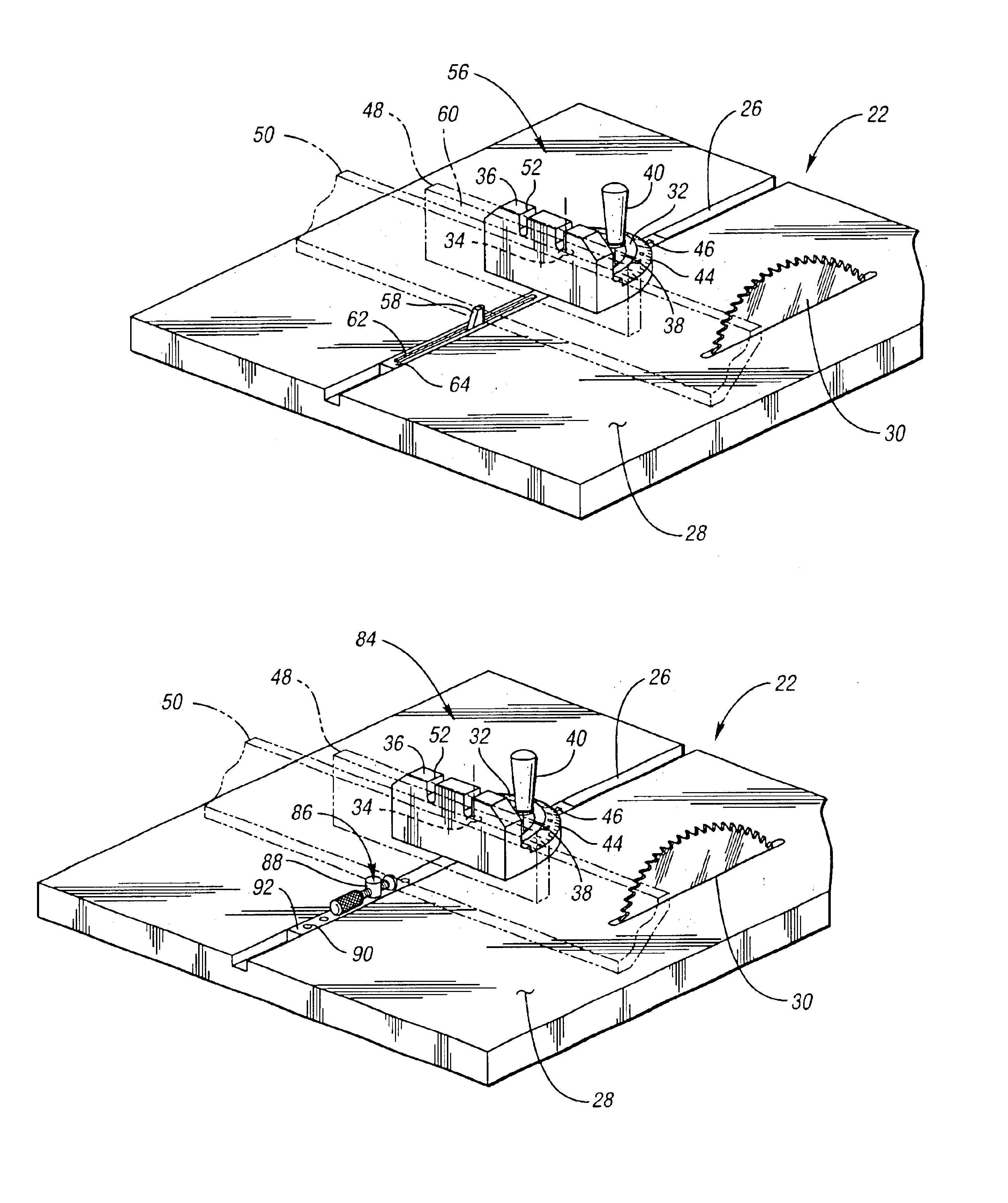
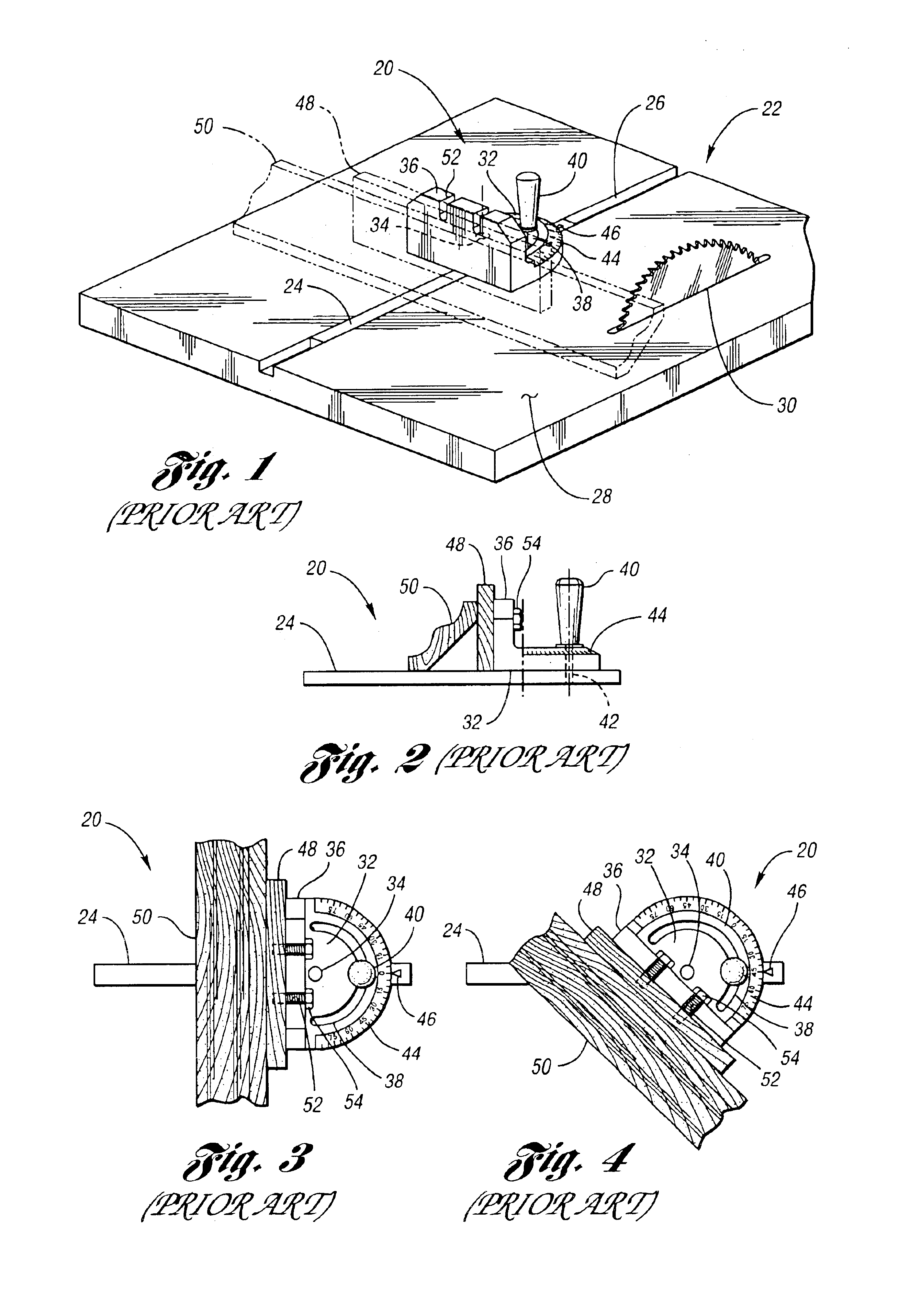
FIGS. 1-4 illustrate a prior art miter gauge 20. FIG. 1 illustrates the miter gauge 20 used in combination with a prior art table saw 22. The table saw 22 includes a table 28 with a saw blade 30 protruding through the table 28. The miter gauge 20 includes a longitudinal base member 24, made of a metal, typically aluminum. The base member 24 cooperates with a recess 26 formed within the table 28 parallel to the saw blade 30.

Fence frame 32 is pivotally mounted to the base member by a pivot pin 34. The pivot pin 34 is perpendicular to the table 28. The fence frame 32 is a semicircular unit formed with an upright planar surface commonly referred to as a fence 36. The fence 36 is typically formed of a high strength molded plastic. An arcuate slot 38 is formed through the fence frame 32 concentric to the pivot pin 34. An adjustment handle 40 cooperates with the arcuate slot 38 and a has a threaded end engaged in a threaded hole 42 in the base member 24 as illustrated in FIG. 2.

A user can ...


PUM


Abstract

The present invention discloses an improved miter gauge for retaining and adjustably positioning a workpiece. The miter gauge includes a fence frame pivotally mounted to a base member for adjusting the workpiece to be cut at a user selected angle. The fence frame includes a fence surface for positioning the workpiece. The fence surface is opposed by a quick-adjusting stopping unit mountable to the base member for clamping the workpiece therebetween.

Description

BACKGROUND OF THE INVENTION1. Field of the InventionThe present invention relates to a miter gauge for retaining and adjustably positioning a workpiece to be cut by a table saw or the like.2. Background ArtMiter gauges are produced in a variety of different types and configurations. These gauges are commonly used for positioning a wooden workpiece to be cut at a user selected angle by a table saw. Miter gauges usually include a fence for abutting the workpiece. They commonly include a semicircular gauge for angular adjustment to a base member which slidingly cooperates within a slotted recess in the saw table top.Conventional miter gauges generally do not include a stop for retaining the workpiece. Retaining a workpiece to be cut by a saw tends to be time consuming to set up and tedious for multiple cutting operations. The stop is frequently unnecessary if the user can easily hold the workpiece against the fence of the miter gauge during the sawing operation. However, not all workpi...

Claims


Application Information

Patent Timeline
IPC IPC(8): B23D47/00B23D47/04B25B5/00B25B5/10B25B5/06B27B25/10B27B25/00B27G5/00B27G5/02B27B27/06
CPCB23D47/04B25B5/06B27G5/023B27B25/10B25B5/10Y10T83/6609Y10T83/7533Y10T83/773Y10T83/745Y10T83/7487Y10T83/7493Y10T83/7553Y10T83/6608Y10T83/758Y10T83/6612
Inventor BRAZELL, KENNETH M.EVERTS, ROBERT G.
Owner ONE WORLD TECH
Why Eureka
Try Eureka