
Varnishing apparatus

a technology of varnishing apparatus and cylinder, which is applied in the direction of rotary letterpress machines, office printing, rotary intaglio printing presses, etc., to achieve the effect of cost-effective fabrication

Inactive Publication Date: 2005-02-01
MANROLANAD AG
View PDF21 Cites 3 Cited by
  • Summary
  • Abstract
  • Description
  • Claims
  • Application Information

AI Technical Summary

Benefits of technology

The mounting of the varnishing mechanism cylinders on the walls of the openings in the side walls of the varnishing apparatus allows the supporting forces for the cylinders of the varnishing mechanism to be introduced directly and at right angles into the side walls, in the longitudinal direction of the side walls. The support of the cylinders is therefore very rigid and exhibits little vibration, which is a precondition of a good print quality and the quality of the varnish application. It is possible for high forces to be applied. The apparatus is constructed using a simple design and, as a result, can be set up cost-effectively. For example, the guide elements may be implemented with commercially available rectilinear guides. The varnishing units are also distinguished by a compact and space-saving design.
The indirect gravure printing process of the present invention allows single-sided varnishing to be carried out with an impression cylinder and two-sided varnishing being carried out in a double printing mechanism. Thus, recto and verso varnishing can be carried out in one printing pass.
The varnishing apparatus of the present invention may optionally be used either to varnish or print in the gravure printing or offset printing process. The inventive varnishing apparatus may be changed over simply from one process to the other. In addition, both printing processes can be used at the same time. Furthermore, one printing process may be used for example for the recto printing and the other printing process for the verso printing. The printing-machine manufacturer can set up the machines for both processes identically from the same components, which permits cost-effective fabrication. In addition, the varnishing apparatuses may be designed with variable format, that is to say they can be re-equipped simply for other formats, that is to say other diameters of the varnishing mechanism cylinders or printing mechanism cylinders and cut lengths. Furthermore, the varnishing apparatus can be changed over quickly to different production variants. In addition, the varnishing apparatus may also be re-equipped as a printing mechanism in a printing machine or at least either for the recto printing or for the verso printing.

Problems solved by technology

This possibility is not provided in flexographic printing, for example, since it is not possible for two relief printing forms to run against each other at the same time.

Method used


Image

  • Varnishing apparatus
  • Varnishing apparatus
  • Varnishing apparatus

Examples


Embodiment Construction

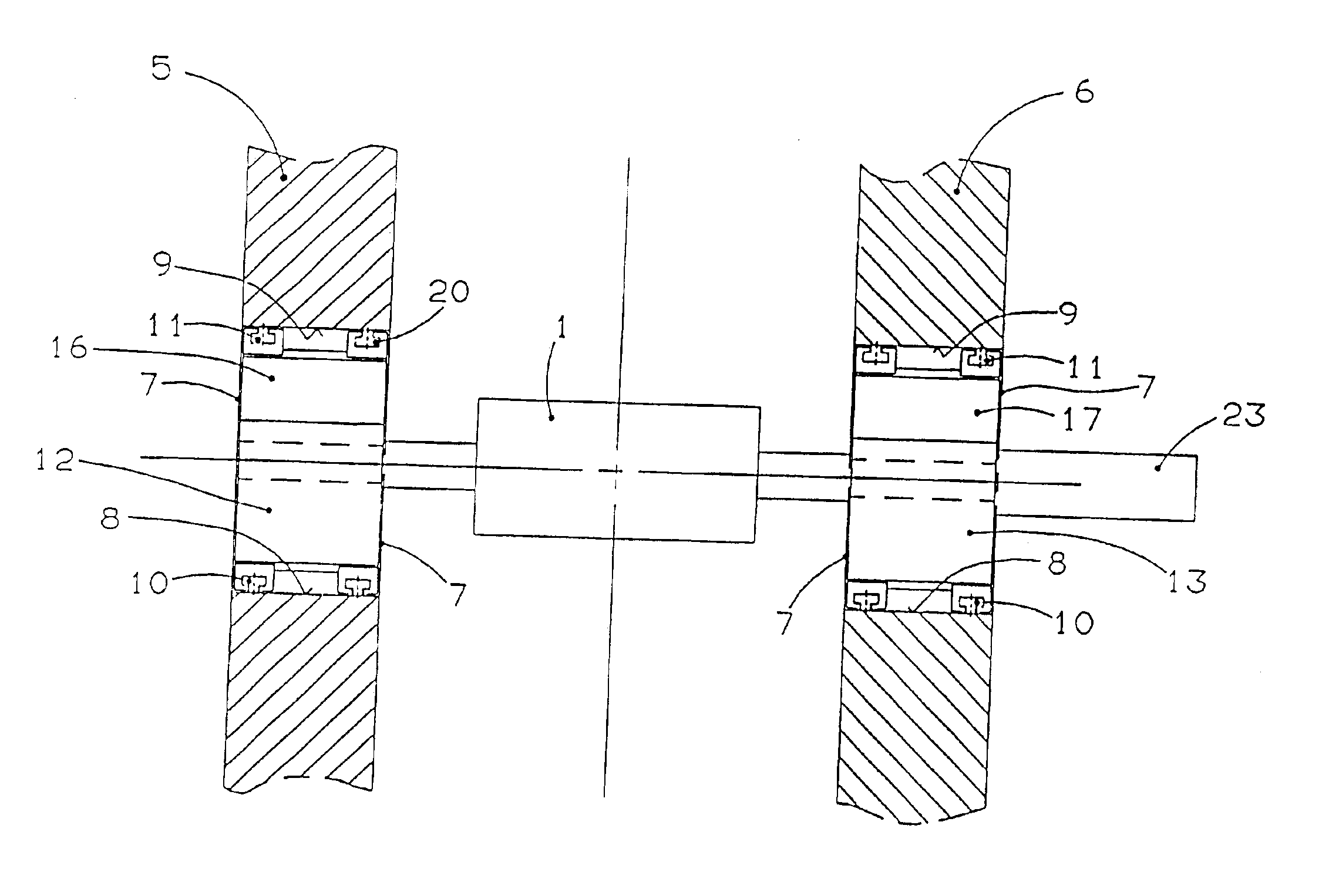
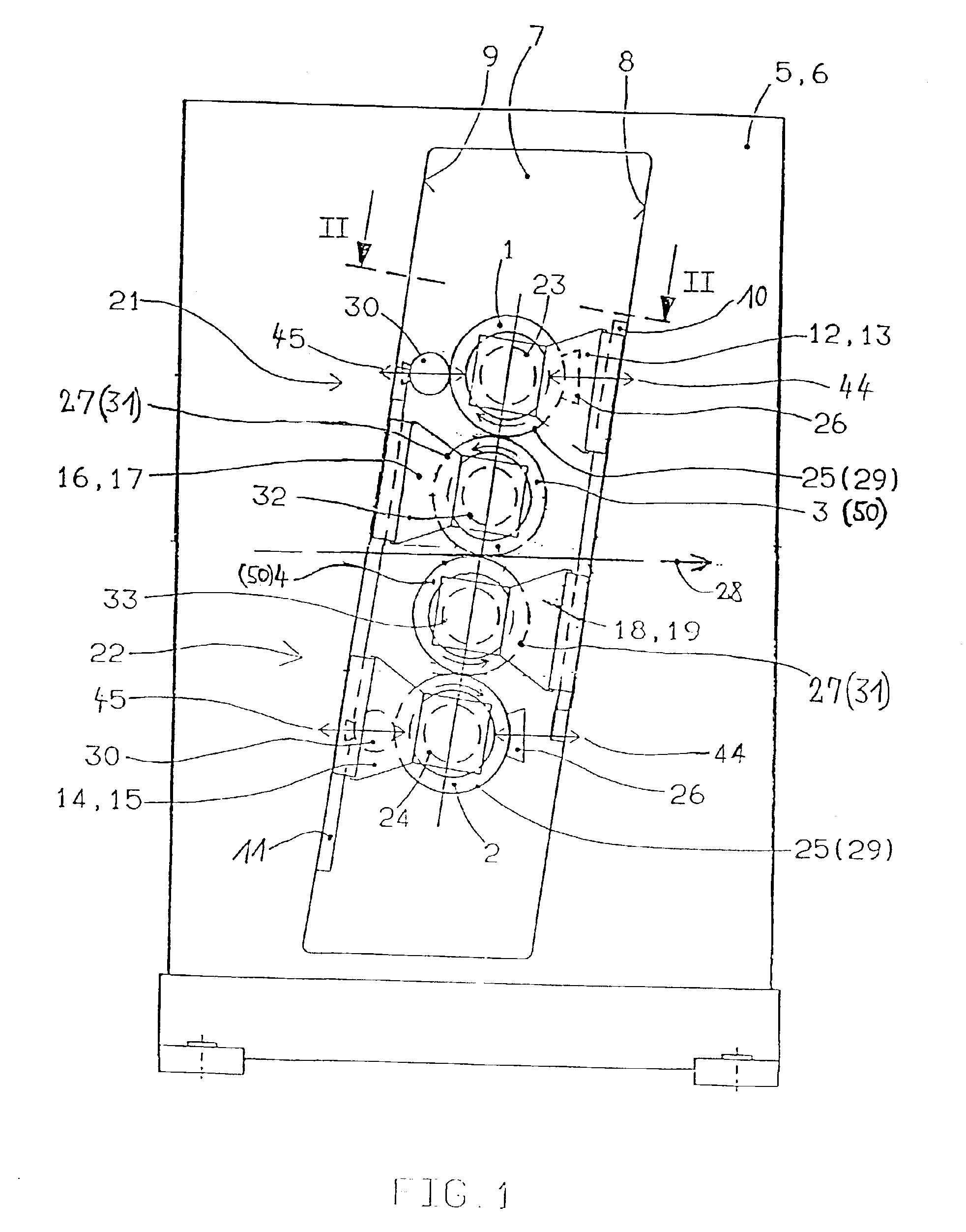
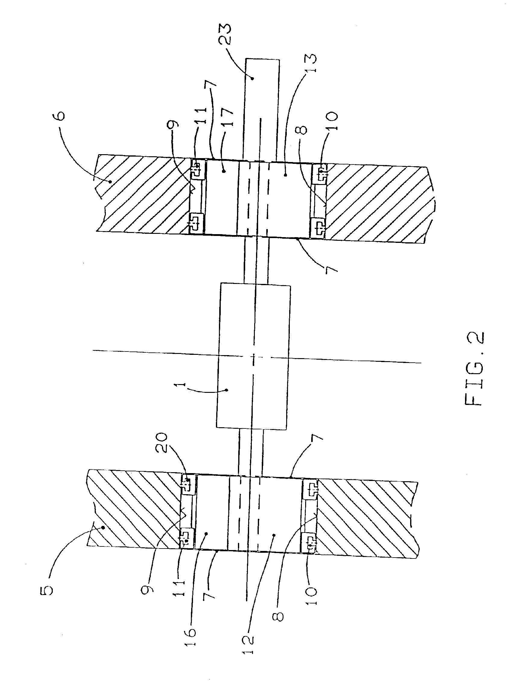
FIGS. 1 and 2 show a varnishing apparatus according to the present invention for use in a web-fed rotary printing machine having two form cylinders 1, 2 and two transfer cylinders 3, 4. Each form cylinder 1, 2 and transfer cylinder 3, 4 includes two opposing ends respectively mounted in side walls 5, 6. Each side wall 5, 6 has an opening 7 therethrough which is bounded by opposing sides 8, 9. The openings 7 may, for example, also be designed as an open slot. Rectilinear guide elements 10, 11 are arranged along the sides 8, 9 of the opening 7.

Each end of the form cylinders 1, 2 includes a journal mounted in a respective slide 12 to 15. The transfer cylinders 3, 4 likewise include journals mounted respectively in slides 16 to 19. The slides 12 to 19 are mounted on the guide elements 10, 11 such that the slides 12 to 19 are movable on the guide elements 10, 11 (see FIG. 2). To create a form-fitting slide guide, the guide elements 10, 11 have a T-shaped cross section with a crossbar tha...


PUM


Abstract

To provide a varnishing apparatus for indirect printing with the lowest possible structural outlay, a varnishing mechanism of the varnishing apparatus for varnishing webs includes a form cylinder and a transfer cylinder, the web running between the transfer cylinders. At least one of the form cylinders bears a gravure printing form such that the web may be varnished on one or both sides.

Description

BACKGROUND OF THE INVENTION1. Field of the InventionThe invention relates to a varnishing apparatus having at least one varnishing mechanism with a form cylinder and a transfer cylinder.2. Description of the Related ArtGerman DE 199 35 173 A1 discloses a varnishing apparatus for varnishing one side of a sheet. The varnishing apparatus includes an applicator cylinder for applying ink to a printing cylinder. A metering system comprising a gravure roll and chamber-type doctor is arranged on the applicator cylinder. A disadvantage of this device is that two varnishing apparatuses configured in this way are required for varnishing two sides of the sheet.SUMMARY OF THE INVENTIONAn object of the present invention to provide a varnishing apparatus for varnishing both sides of a sheet by indirect printing, which is designed with the lowest possible constructional outlay.According to the present invention, the object is achieved by a varnishing apparatus for varnishing a web including first a...

Claims


Application Information

Patent Timeline
Patent Type & Authority Patents(United States)
IPC IPC(8): B41F23/08B41F23/00
CPCB41F23/08
Inventor PETERSEN, GODBERSTAMME, RAINER
Owner MANROLANAD AG
Learn More