
Mortar buggy

a technology for transporting vehicles and mortar buggy, which is applied in the directions of transportation and packaging, loading/unloading vehicle arrangment, transportation items, etc., can solve the problems of operator slippage on the platform, adversely affecting the effective control of the mortar buggy, and the prior art process requires considerable manual dexterity and substantial strength capabilities, so as to achieve quick and easy removal and replacement, less time and labor.

Inactive Publication Date: 2005-02-01
TORO CO THE
View PDF41 Cites 21 Cited by
  • Summary
  • Abstract
  • Description
  • Claims
  • Application Information

AI Technical Summary

Benefits of technology

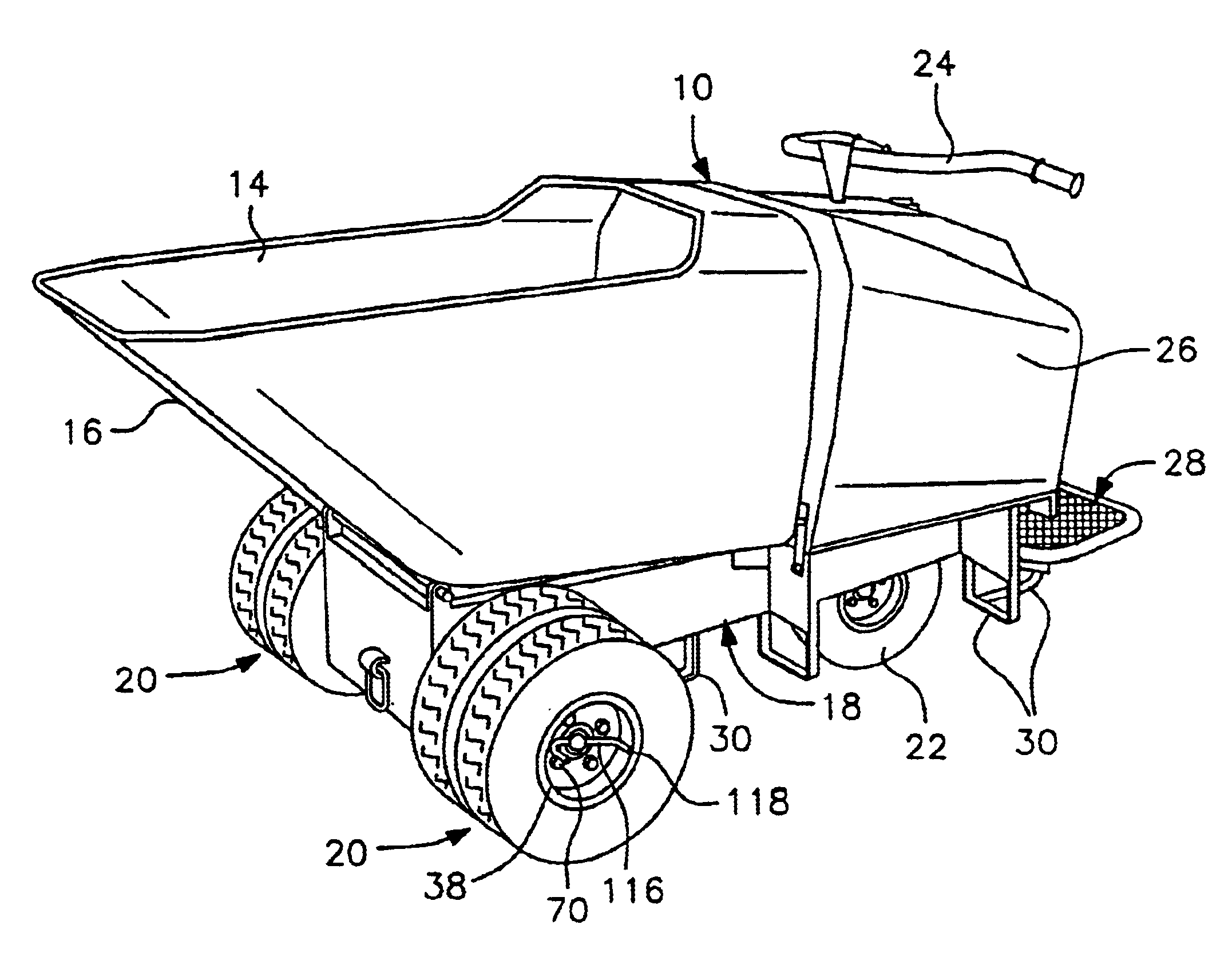
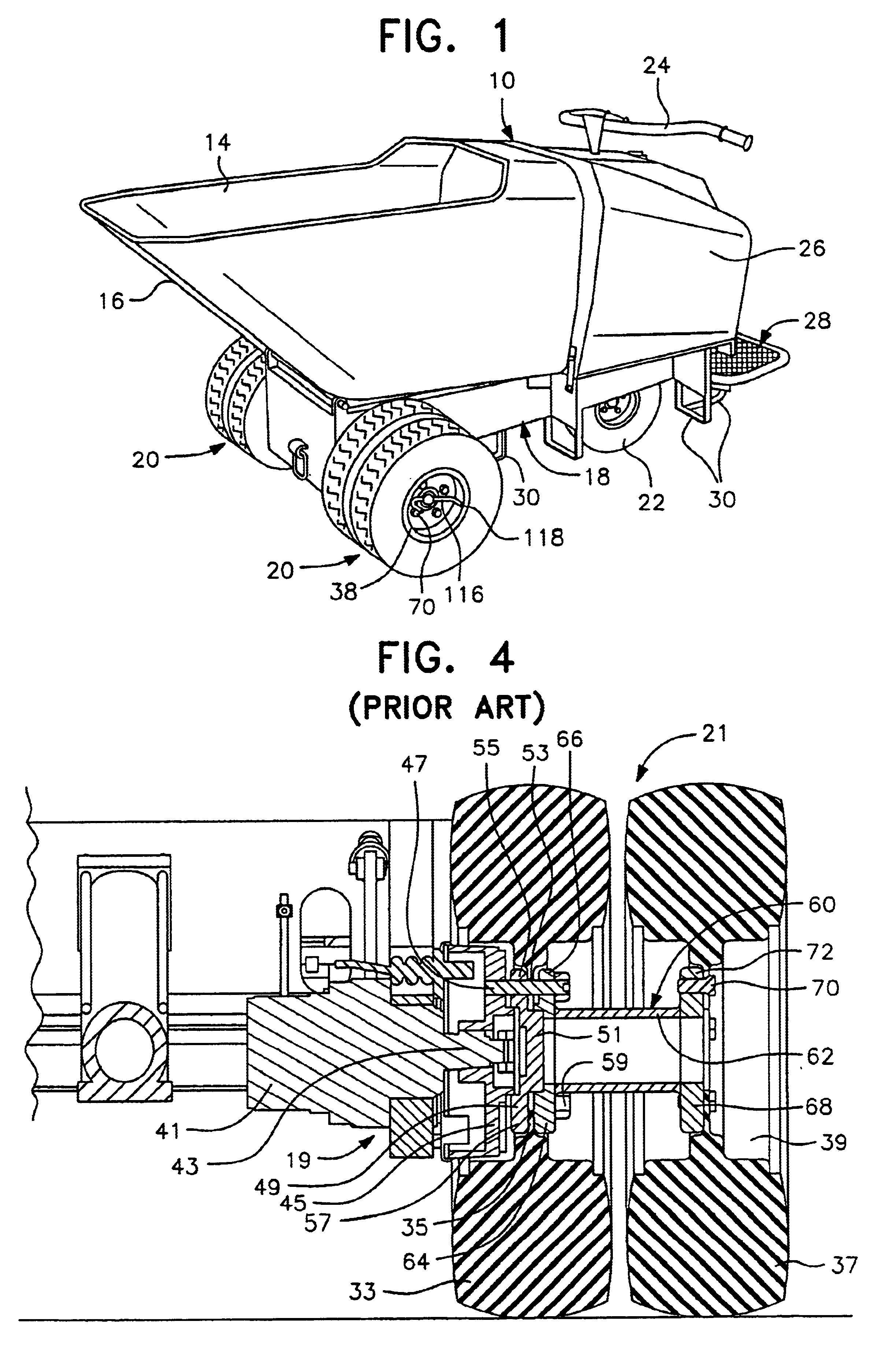
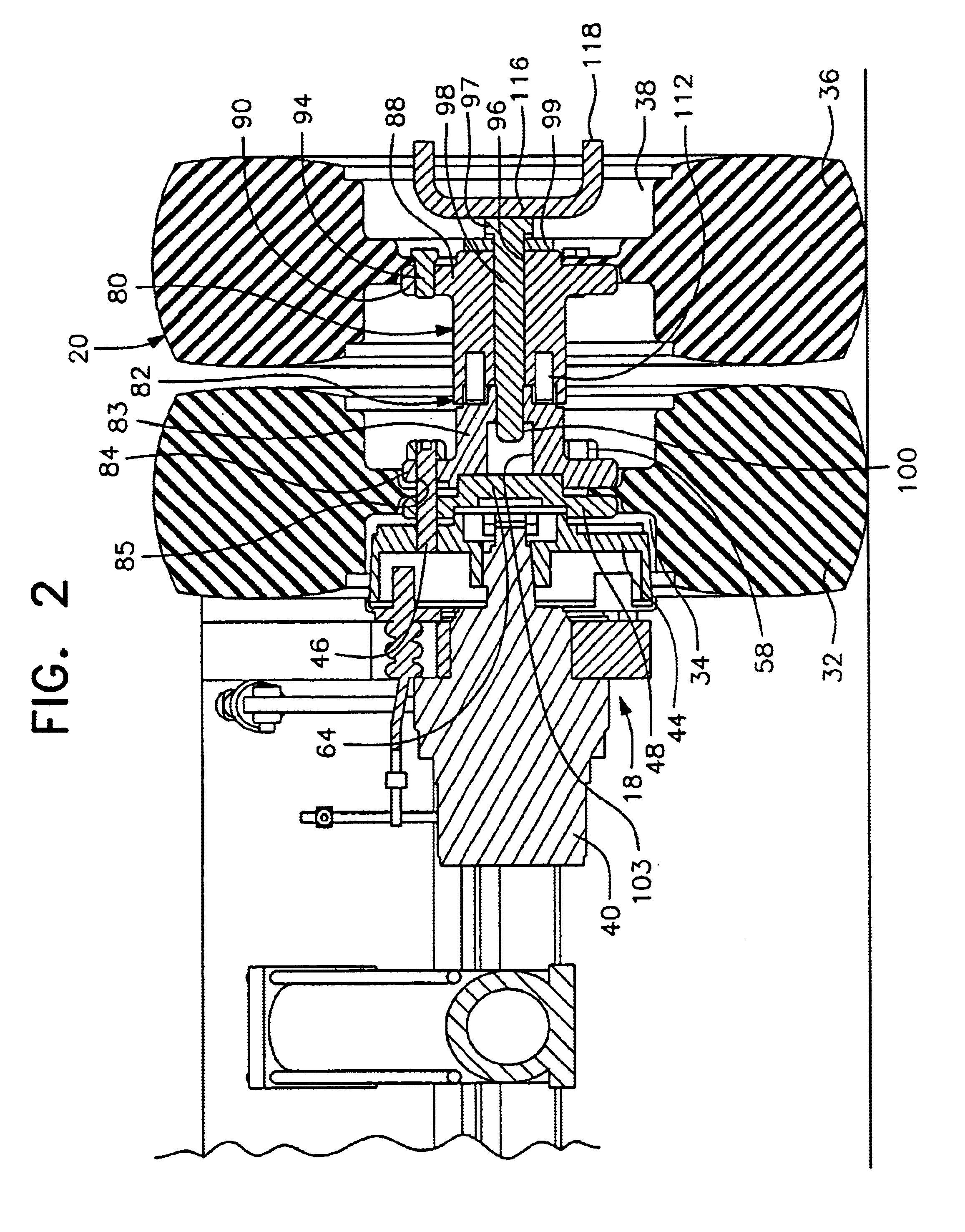
The mortar buggy with quick release hub of the present invention enables the outer tires and wheels of dual wheel assemblies at the front and each side of a mortar buggy to be quickly and easily removed and replaced in less time and with less labor thereby enabling a mortar buggy to quickly move through a narrow doorway in order to deliver more mortar to a job site in a given time. The quick release hub of the outer tires and wheels does not require any special tools or any lifting equipment and reduces the possibility of hub components becoming misplaced or covered with dirt and debris which can occur due to job sites often having loose debris, dirt and the like. The elimination of a lifting apparatus necessary to lift prior art mortar buggies off the ground surface provides a safer, faster and easier operation. The mortar buggy using the quick release hub of the present invention may be driven so that the inner tire engages and is supported by a block with the outer tire and wheel then being elevated so that it can be easily removed and replaced when necessary.
An additional object of this invention to be specifically enumerated herein is to provide a mortar buggy in accordance with the preceding objects and which will conform to conventional forms of manufacture, be of simple construction and easy to use so as to provide a device that will be economically feasible, long lasting and relatively trouble free in operation.

Problems solved by technology

Additionally, the outer tire and wheel, the lug nuts and bolts, and the tubular axle extension become separate components subject to being misplaced or covered with dirt or debris.
Also, the procedure in the prior art requires considerable manual dexterity and substantial strength capabilities in aligning the lug openings in the wheels with the lug bolts and assembly of the lug nuts and lug bolts when the outer tire and wheel is reassembled after passage of the mortar buggy through a doorway or other similar restricted space.
Prior art operator platforms on mortar buggies are sometimes perforated and constructed in a manner which enables dirt, mud, water and debris to become deposited on the platform and feet of an operator during operation of the mortar buggy which adversely affects effective control of the mortar buggy and can cause the operator to slip on the platform.

Method used


Image

  • Mortar buggy
  • Mortar buggy
  • Mortar buggy

Examples


Embodiment Construction

Although only one preferred embodiment of the invention is explained in detail, it is to be understood that the invention is not limited in its scope to the details of construction and arrangement of components set forth in the following description or illustrated in the drawings. The invention is capable of other embodiments and of being practiced or carried out in various ways. Also, in describing the preferred embodiment, specific terminology will be resorted to for the sake of clarity. It is to be understood that each specific term includes all technical equivalents which operate in a similar manner to accomplish a similar purpose.

Referring specifically to FIGS. 1-3, a mortar buggy incorporating the present invention therein is generally designated by reference numeral 10 and includes a pivotally supported hopper or bucket 12 having an open upper end area 14 and a slanted front wall 16 with a conventional hydraulic structure (not shown) provided to tilt the rearward end of the h...


PUM


Abstract

A quick release hub for the outer tires and wheels of dual wheel assemblies on a vehicle such as a mortar buggy to enable the vehicle to move through a narrow doorway or other passageway having a width less than the total distance between the outermost surfaces of the outer tires. The quick release hub includes a two component hub secured together by a single fastening device which enables quick and easy removal and replacement of the outer tires and wheels. A combination engine electrical control switch for the mortar buggy engine automatically controls a fuel supply valve to open and close the fuel valve in response to the engine control switch. An operator's platform and brake actuator are mounted at the rear of the mortar buggy with the brake actuator extending transversely at the forward portion of the platform to enable an operator to use either foot to operate the brake actuator.

Description

BACKGROUND OF THE INVENTION1. Field of the InventionThe present invention generally relates to a powered material transporting vehicle generally known in the art as a mortar buggy for moving material, primarily mortar, concrete, gravel, dirt or other material capable of being placed in a hopper or bucket for transport to a job site and dumped by tilting the hopper or bucket. The mortar buggy includes a powered pivotal hopper, dual supporting and driving wheels at each side of the front of the buggy, dual wheels on a single steerable rear axle at the rear, a rear operator's platform and controls accessible to the operator. The mortar buggy of the present invention includes structure for quick release of the outer wheel and tire thereon from each set of dual front wheels in order to reduce the maximum width of the buggy. This enables the buggy to pass through a narrow doorway or the like in order to gain access to a job site where the contents of the mortar buggy hopper will be used i...

Claims


Application Information

Patent Timeline
IPC IPC(8): B60B11/00
CPCB60B11/00
Inventor BURT, CHRISTOPHER M.BOOR, GUY W.
Owner TORO CO THE
Learn More