Ground effect airplane

a ground effect and aircraft technology, applied in the field of vehicles, can solve the problems of airships that are not airships with relatively slow cruising speed, airships that are not practical for reliable overseas cargo transportation, etc., and achieve the effect of efficiently flowing into and out of ground

Inactive Publication Date: 2005-02-01
THE BOEING CO
View PDF30 Cites 43 Cited by
  • Summary
  • Abstract
  • Description
  • Claims
  • Application Information

AI Technical Summary

Benefits of technology

In one preferred form, the present invention provides an aircraft having a fuselage, a wing assembly, an altitude control system and a plurality of independent and steerable landing gear units. The fuselage defines a central storage cavity having a length of at least 100 feet, a height of at least 16 feet and a width of at least 24 feet. The wing assembly extends through and is coupled to the fuselage in an unswept manner to provide the aircraft with a wingspan of at least 300 feet. The wing assembly defines a pair of wing storage cavities each of which being located on an opposite side of the fuselage. The wing assembly has a moderate aspect ratio of at least 3.5 to permit the aircraft

Problems solved by technology

However, considerations for the size of the hanger for housing the airship, the stresses on the airship structure, the maneuverability of the airship, the airship's relatively slow cruising speed and the dependence on weather conditions render airships impractical for reliable overseas cargo transport.
Conventional ground effect aircraft, however, are not well suited for the overseas transport of a high volume of cargo.
Accordingly, large swells could prevent operations or necessitate alternative routes which would tend to increase costs and disrupt delivery schedules.
Furthermore, when the known ground-effect aircraft are scaled up in size to accommodate high volume carg

Method used


Image

  • Ground effect airplane
  • Ground effect airplane
  • Ground effect airplane

Examples


Embodiment Construction

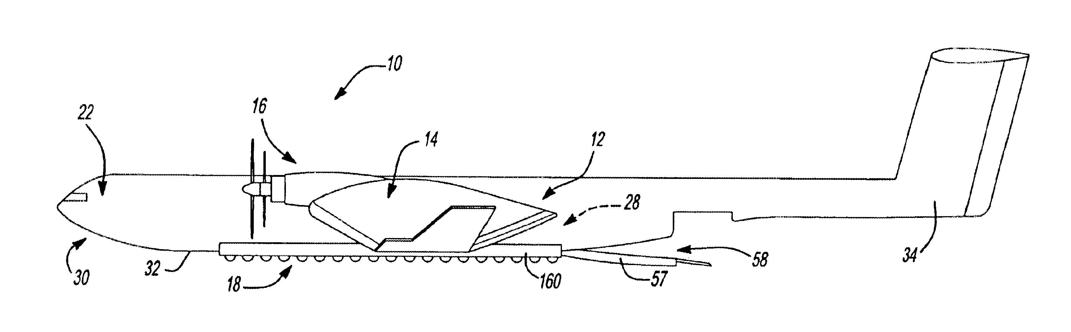
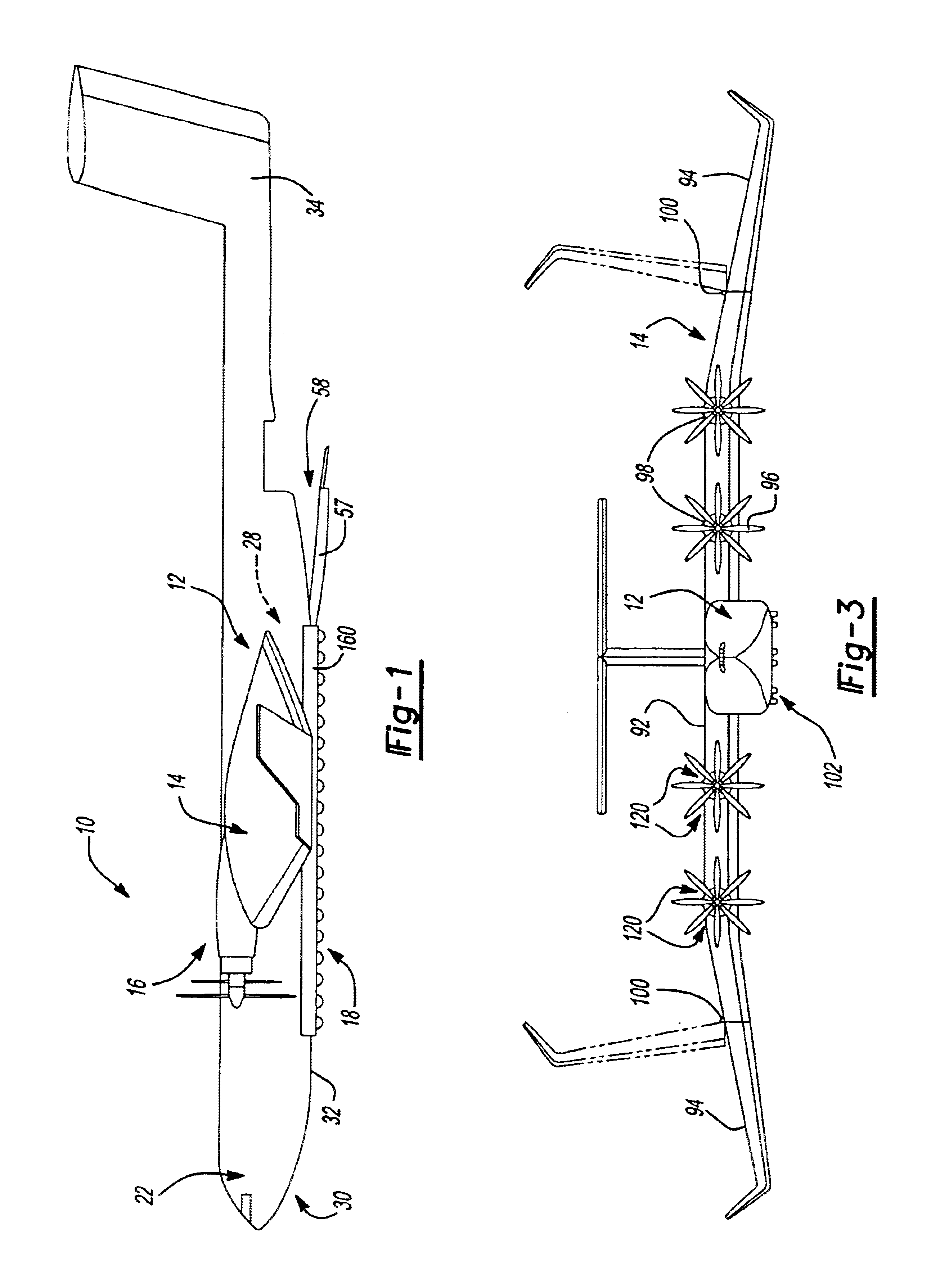
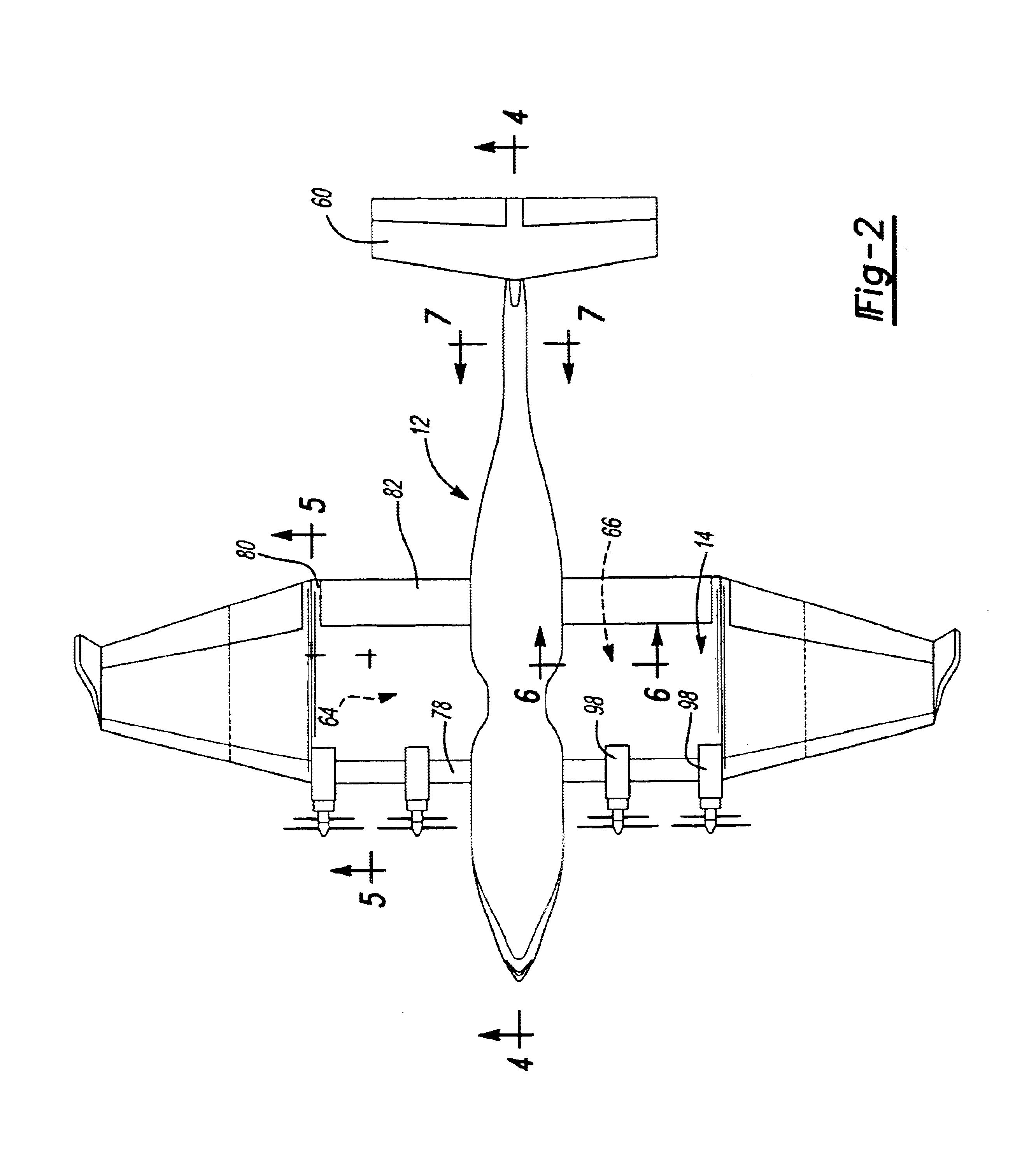
With reference to FIG. 1 of the drawings, a ground-effect cargo transport aircraft constructed in accordance with the teachings of the present invention is generally indicated by reference numeral 10. The aircraft 10 is illustrated to include a fuselage 12, a wing assembly 14, a propulsion system 16, a landing gear system 18.

The aircraft 10 is extremely large in size, being approximately twice as big and six times as heavy as any other aircraft that is presently in existence. The aircraft 10 has a length of at least 100 feet and a wingspan of at least 300 feet. In the example provided, the aircraft has a length of 420 feet and a wingspan of 480 feet. The large size of the aircraft 10 tends to reduce operating costs by improving the aerodynamic efficiency of the aircraft 10 in ground-effect operation and reducing labor cost per unit of cargo transported, for example.

Structural efficiency factors into the operating cost of any aircraft, since weight capacity that is not allocated to t...


PUM


Abstract

An extremely large aircraft which is suitable for overseas cargo transport and which includes a fuselage defining a central storage cavity, a wing assembly defining a pair of wing storage cavities, an altitude control system, and a plurality of independently steerable landing gear units. The central storage cavity has a length, height and width of at least 100 feet, at least 16 feet and at least 24 feet, respectively. The wing assembly has a wingspan of at least 300 feet and is configured with a moderate aspect ratio to permit both ground-effect and high altitude operation. The altitude control system controls the aircraft in ground effect such that the aircraft is maintained at about a predetermined altitude. The landing gear units are coupled to the fuselage and are arranged in at least two discrete columns and at least ten discrete rows. The central storage cavity and the wing storage cavities are configured to receive cargo including intermodal re-usable cargo containers.

Description

FIELD OF THE INVENTIONThe present invention generally relates to a vehicle for overseas and overland cargo transport and more particularly to a ground-effect aircraft that is configured to permit the relatively efficient, rapid and cost-effective overseas and overland transport of cargo.BACKGROUND OF THE INVENTIONThe overwhelming majority of all overseas cargo is presently transported by ship. As compared to the transport of overseas cargo via conventional high altitude, high-speed aircraft, overseas cargo transport via ship is often 4 to 5 times slower but less expensive by a factor of ten. As such, only about one percent of all overseas cargo is time sensitive enough to necessitate shipment via conventional air transport. Given the gaps in the cost and transit time between ships and conventional air transport, there is an apparent need in the art for an alternative transport vehicle that facilitates the relatively efficient, rapid and cost-effective overseas transport of cargo.Lar...

Claims


Application Information

Patent Timeline
IPC IPC(8): B60V1/08B60V1/00B64C1/00B64D35/00B64D9/00B64C3/00B64C3/16B64C3/56B64D35/08
CPCB60V1/08B64C1/0009B64C3/16B64C3/56B64D35/08B64D9/00Y02T50/46Y02T50/12Y02T50/145Y02T50/10Y02T50/40
Inventor HOISIGNTON, ZACHARY C.RAWDON, BLAINE K.
Owner THE BOEING CO
Why Eureka
Try Eureka