
Spot and chamfer drill insert

a drill insert and chamfer technology, applied in the field of drills, can solve the problems of increasing the thrust of the drill bit, generating more heat at the cut, and inability to cut stable, so as to achieve accurate spot cut and improve the effect of point geometry

Inactive Publication Date: 2005-02-01
ALLIED MASCH & ENG CORP
View PDF11 Cites 15 Cited by
  • Summary
  • Abstract
  • Description
  • Claims
  • Application Information

AI Technical Summary

Benefits of technology

An object of the present invention is to provide a drill insert with an improved point geometry that can provide an accurate spot cut and, if desired, a finish hole chamfer in one operation. These and other advantages are provided by a drill insert comprising a drill insert body having at least a first end opposite a second end and a first face side opposite a second face side; wherein the first end of the drill insert body is a generally planar surface and the second end has at least two main cutting edges formed thereon at a first inclusive angle, a web formed between the two main cutting edges, and a web thinning notch formed on either side of the web, forming web thinning cutting edges at a second inclusive angle and separated from each other by a chisel; wherein the chisel is formed by the intersection of at least a primary web thin clearance surface behind each web thinning cutting edge; wherein the primary web thin clearance surface is formed at a primary web thin clearance angle with respect to a projected plane normal to a plane through the web thin cutting edge and parallel to the longitudinal axis of the insert, wherein the projected plane is tangent to the web thin cutting edge.

Problems solved by technology

These inserts had excessive clearance at the point which increased the length of the chisel edge resulting in unstable cutting requiring increased thrust and generating more heat at the cut.

Method used


Image

  • Spot and chamfer drill insert
  • Spot and chamfer drill insert
  • Spot and chamfer drill insert

Examples


Embodiment Construction

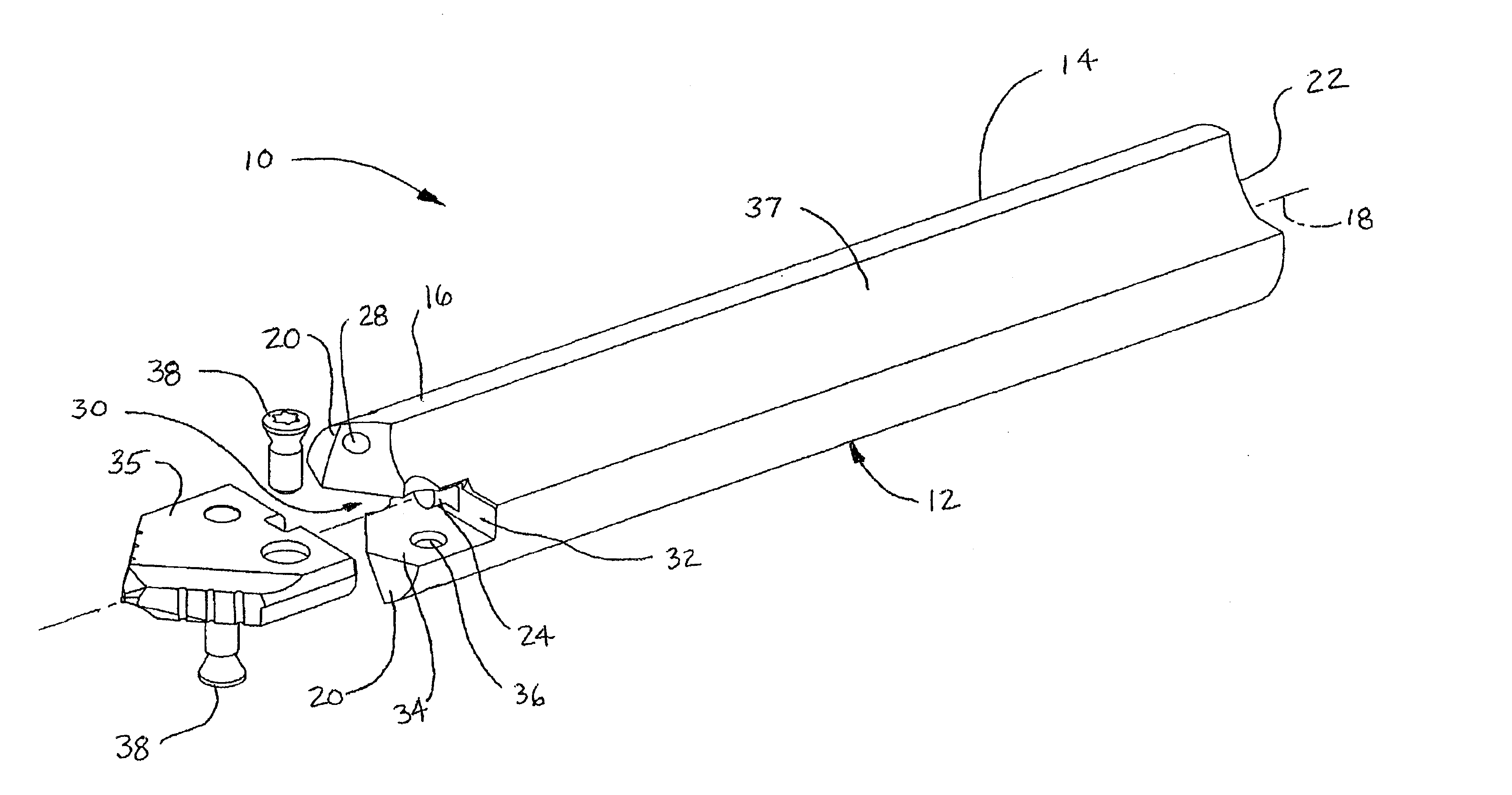
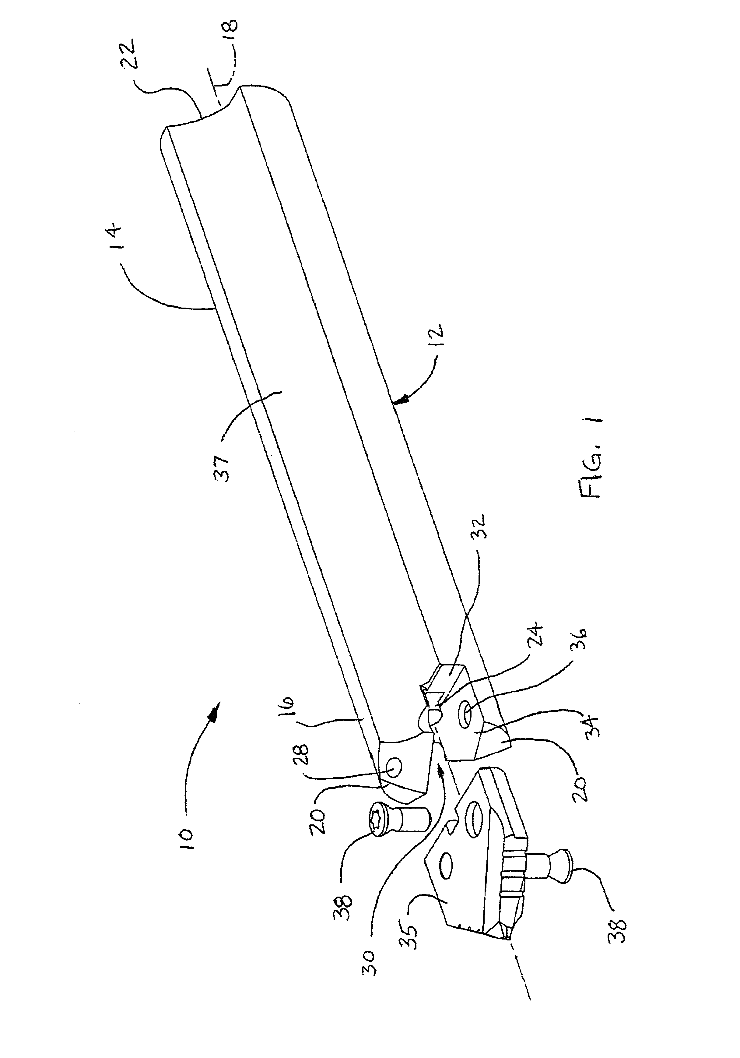
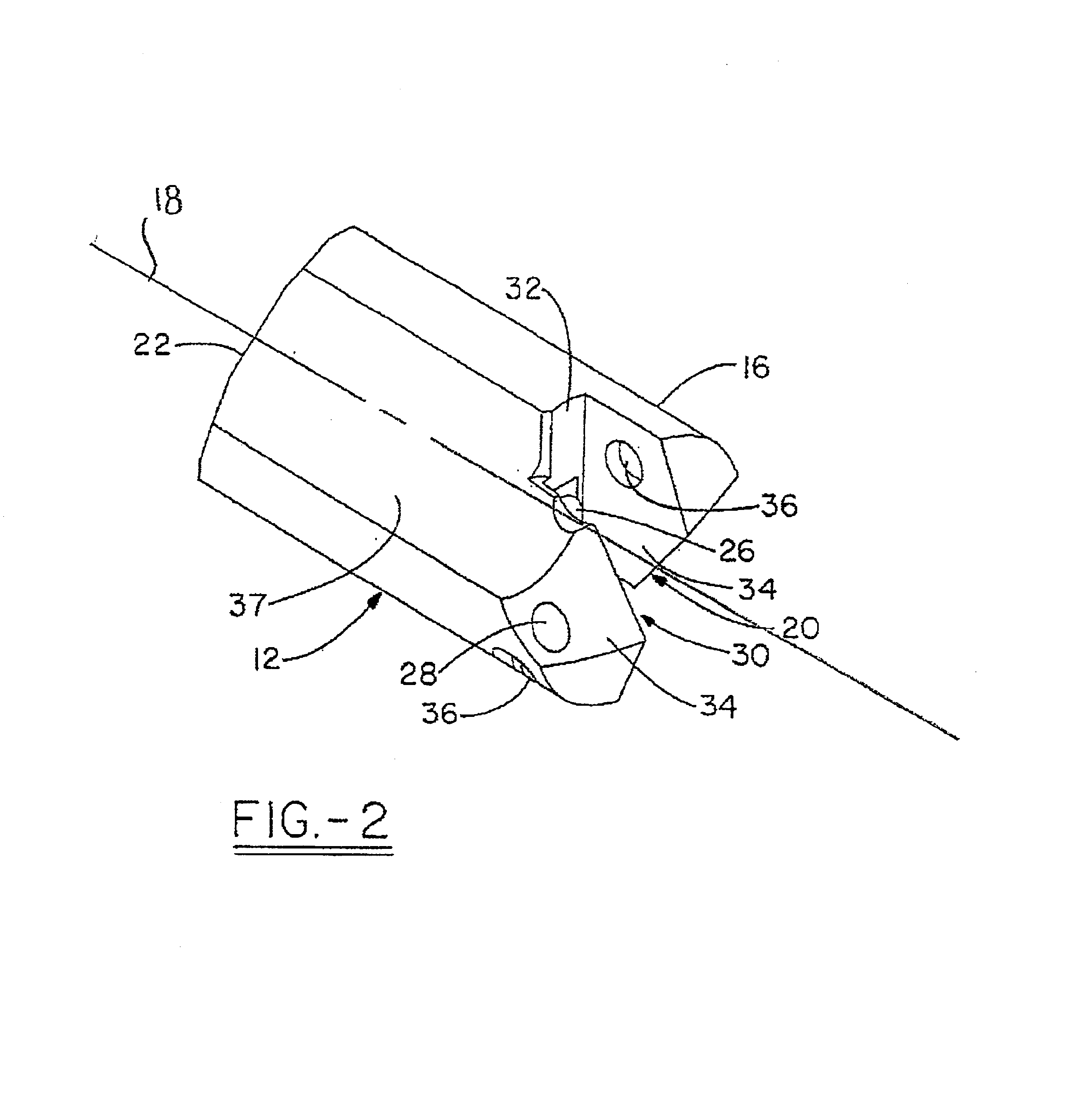
Turning now to a preferred embodiment of the invention, FIG. 1 illustrates a drill tool assembly 10 generally indicated. Drill tool assembly 10 comprises a holder 12, which has a body 14 and head portion 16 associated therewith. In the preferred embodiment, holder 12 has, in general, a cylindrical shape with a first end 20 and second end 22. As also shown in FIG. 2, the first end 20 of holder 12 has a clamping or holder slot 30, which may extend across the entire diameter of the head portion 16 or, at least, over a center portion thereof at the general location of the rotational axis 18 of holder 12. The holder slot 30 has a bottom wall 32 positioned in substantially perpendicular orientation relative to the rotational axis 18 of the holder 12. In the preferred embodiment, the assembly 10 may further include a locating boss or dowel pin 24, which is positioned precisely with respect to the axis 18 and extends from the bottom wall 32 of the holder slot 30. The pin 24 may be positione...


PUM

PropertyMeasurementUnit
inclusive angleaaaaaaaaaa
included anglesaaaaaaaaaa

Abstract

The present invention relates to a spot and chamfer drill insert which can be utilized to create accurately located spots for subsequent drilling operations while simultaneously providing a chamfer for the finished hole. The present invention utilizes web thin clearance surfaces that are formed at web thin clearance angles, wherein the web thin clearance angles are oriented with respect to a projected plane normal to a plane through the web thin cutting edge and parallel to the longitudinal axis of the insert, wherein the projected plane is tangent to the web thin cutting edge.

Description

TECHNICAL FIELDThe present invention relates generally to a drill having a specialized drill insert for boring holes into metals. More specifically the invention relates to an improved spot and chamfer drill insert which can be utilized to create accurately located spots for subsequent drilling operations while simultaneously providing a chamfer for the finished hole.BACKGROUND OF THE INVENTIONIn typical drilling operations, especially with deep-drilled holes, the hole is first accurately located by using a spot drill. A spot drill improves the positional accuracy of subsequent drilling operations. After the spot drilling operation is complete, a standard drill is used to drill the hole to the desired depth. A third drill is then typically used to put a chamfer on the edge of the drilled hole. Accordingly, the drilled hole requires at least three drill tools, more if the hole must be trued with a boring cutter and / or reamed to size with a reamer. This takes significant time for at l...

Claims


Application Information

Patent Timeline
Patent Type & Authority Patents(United States)
IPC IPC(8): B23B51/00
CPCB23B51/0009B23B2251/14B23B2251/48B23B2251/50Y10T408/909Y10S408/713Y10T408/9098Y10T408/906B23B51/00035
Inventor STOKEY, TIMOTHY G.
Owner ALLIED MASCH & ENG CORP
Learn More