Continuously variable power-split transmission

a technology of power-split transmission and variable power, which is applied in the direction of belt/chain/gearing, friction gearing, belt/chain/gearing, etc., can solve the problem of reducing the power transmission efficiency of the variator, reducing the size of the variator, and accelerating damage to the power roller and the disk. the effect of high transmission efficiency

Inactive Publication Date: 2005-02-01
JATCO LTD
View PDF9 Cites 151 Cited by
  • Summary
  • Abstract
  • Description
  • Claims
  • Application Information

AI Technical Summary

Benefits of technology

VDI Berichte Nr. 1565, 2000, P.256, Bild 20 discloses a continuously variable power-split transmission wherein the rotational input is first split by a planetary gear mechanism and the split rotation is then input into a variator and a fixed gear transmission mechanism. According to this transmission, the rotational input is split between the variator and the fixed gear transmission mechanism in both low speed mode and high speed mode, and the rotational input passing through the variator is reduced as a result. Therefore, a high degree of transmission efficiency is achieved in both modes and the variator may be reduced in size.
It is therefore an object of this invention to reduce slippage between a power roller and a disk in a continuously variable power-split transmission.

Problems solved by technology

In high speed mode, however, the thrusting force applied to the input disk by the mechanical loading mechanism for supporting the power rollers is not commensurate with the torque which is transmitted by the variator, and as a result the amount of thrusting force required for supporting the power rollers may be lacking in relation to the transmitted torque.
When the thrusting force is insufficient, slippage occurs between the power rollers and the input disk or output disk, causing a reduction in the power transmission efficiency of the variator and expediting damage to the power rollers and disks.

Method used


Image

  • Continuously variable power-split transmission
  • Continuously variable power-split transmission
  • Continuously variable power-split transmission

Examples


Embodiment Construction

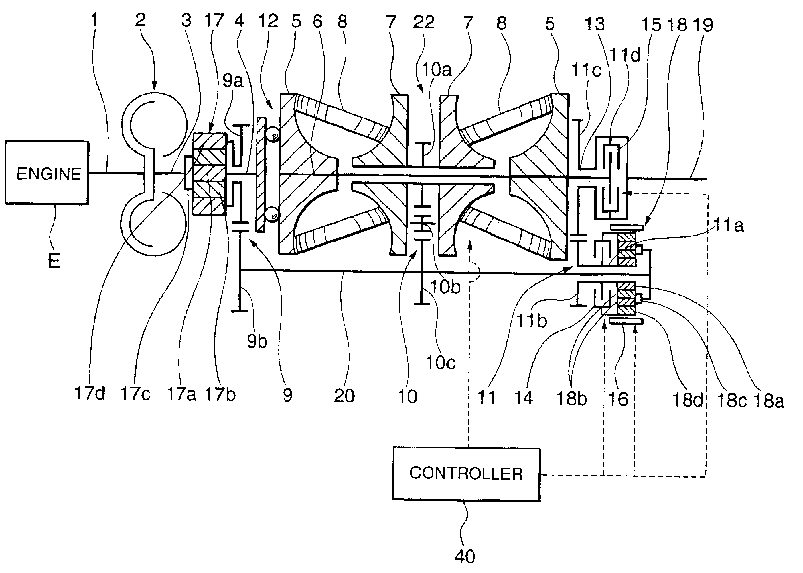
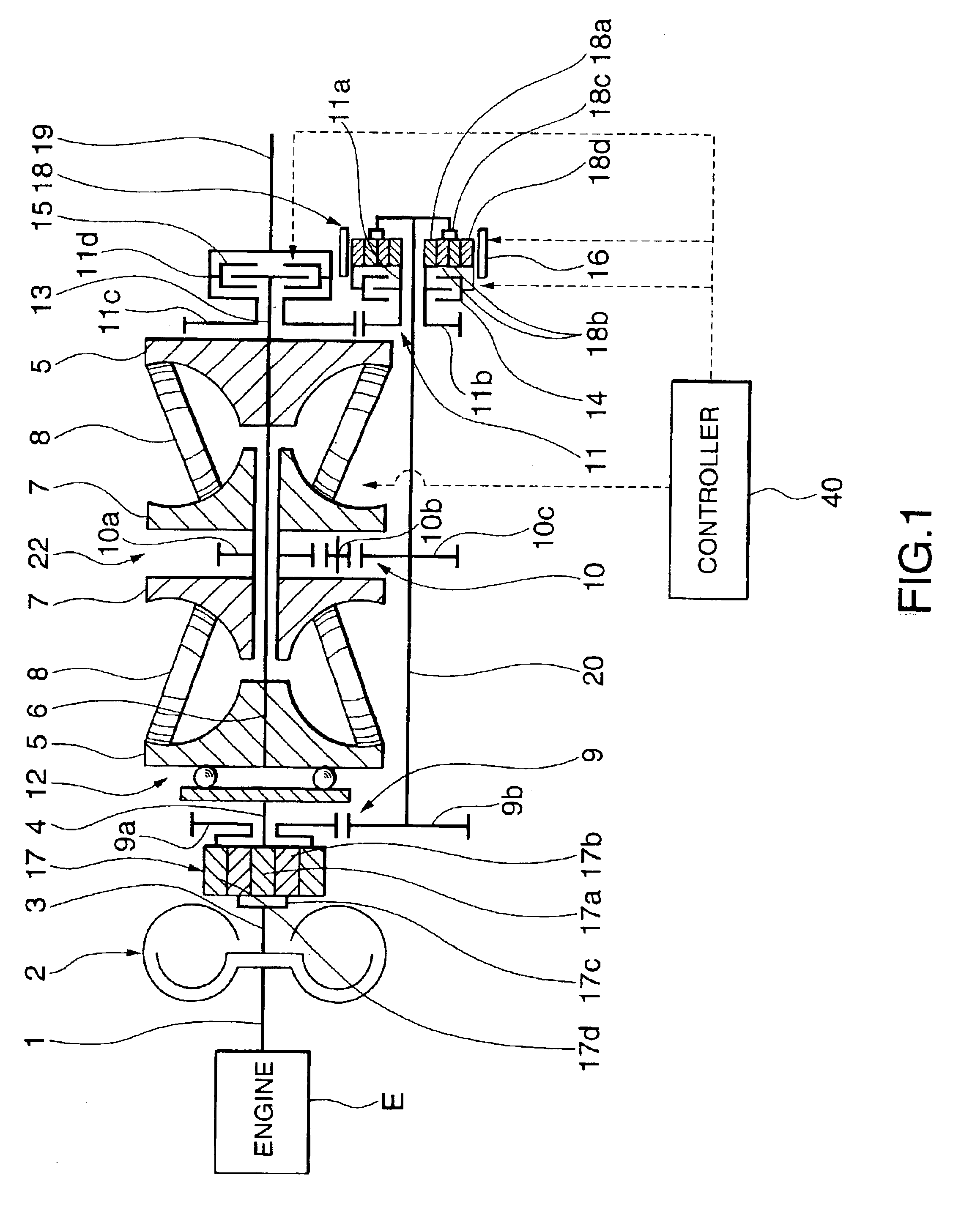
Referring to FIG. 1, an input shaft 1 of a vehicle engine E outputs rotational torque through a vehicle starting device 2 such as a torque converter to an input shaft 3.

The input shaft 3 is coupled to a carrier 17c of a first planetary gear mechanism 17. A part of the rotational torque which is transmitted from the input shaft 3 to the carrier 17c is transmitted to a sun gear 17a of the first planetary gear mechanism 17, and the remaining rotational torque is transmitted to a ring gear 17d thereof. For this purpose, a plurality of pinions 17b each of which meshes with the sun gear 17a and the ring gear 17d are supported by the carrier 17c. Herein, the carrier 17c represents a first rotating member, the sun gear 17a represents a second rotating member, and the ring gear 17d represents a third rotating member in the claims.

The rotational torque which is transmitted to the sun gear 17a is transmitted to a mechanical loading mechanism 12 through a variator input shaft 4 which is dispose...


PUM


Abstract

The second platenary gear mechanism 18 is a so-called double pinion type planetary gear comprising a sun gear 18a, paired pinions 18b, a carrier 18c which supports the pinions, and a ring gear 18d. The pinions 18b of eeach pair meshes with each other in a state where one of the paired pinions 18b meshes with the sun gear 18a while the other one of the paired pinions 18b meshes with the ring gear 18d. The carrier 18c is coupled to the countershaft 20 and the sun gear 18a is connected to a shaft 11a which is coupled to a gear 11b of a third gear unit 11.

Description

FIELD OF THE INVENTIONThis invention relates to a continuously variable power-split transmission using a toroidal variator.BACKGROUND OF THE INVENTIONJP11-063147 published by the Japanese Patent Office in 1999, discloses a continuously variable power-split transmission for a vehicle. This continuously variable power-split transmission is provided with a toroidal continuously variable transmission mechanism (variator) and a fixed speed ratio transmission mechanism having identical rotational inputs. The outputs of these transmission mechanisms are input into a planetary gear mechanism. When the vehicle is running in a high speed mode, the rotational output of the planetary gear mechanism is applied for driving the wheels of the vehicle, and when the vehicle is running in a low speed mode, the rotational output of the variator is applied for driving the wheels of the vehicle, thereby enlarging the speed ratio range and achieving a high power transmission efficiency.In this continuousl...

Claims


Application Information

Patent Timeline
Patent Type & Authority Patents(United States)
IPC IPC(8): F16H37/06F16H37/08F16H37/02F16H15/38
CPCF16H37/086F16H2037/104F16H2037/0866
Inventor SUMI, YASUO
Owner JATCO LTD
Why Eureka
Try Eureka