Rotating shadowband pyranometer

a shadowband pyranometer and rotating technology, applied in the field of pyranometers, can solve the problems of wear and bind, complicated mechanical structure of the supporting and driving shadowband, affecting the reliability and life of the drive system, etc., and achieve the effect of less cos

Inactive Publication Date: 2005-02-01
RWE SCHOTT SOLAR
View PDF7 Cites 26 Cited by
  • Summary
  • Abstract
  • Description
  • Claims
  • Application Information

AI Technical Summary

Benefits of technology

The object of the invention is to provide a rotating shadow band pyranometer that overcomes the limitations of the ATI device. A more specific object is to provide a rotating shadow band pyranometer that employs a direct dri

Problems solved by technology

The ATI rotating shadow band pyranometer functioned well but suffered from the limitation that the mechanical structure for supporting and driving the shadow band was complicated and hence expensive.
Friction in the gear system would cause it to wear out and bind over time.
Also

Method used


Image

  • Rotating shadowband pyranometer
  • Rotating shadowband pyranometer
  • Rotating shadowband pyranometer

Examples


Embodiment Construction

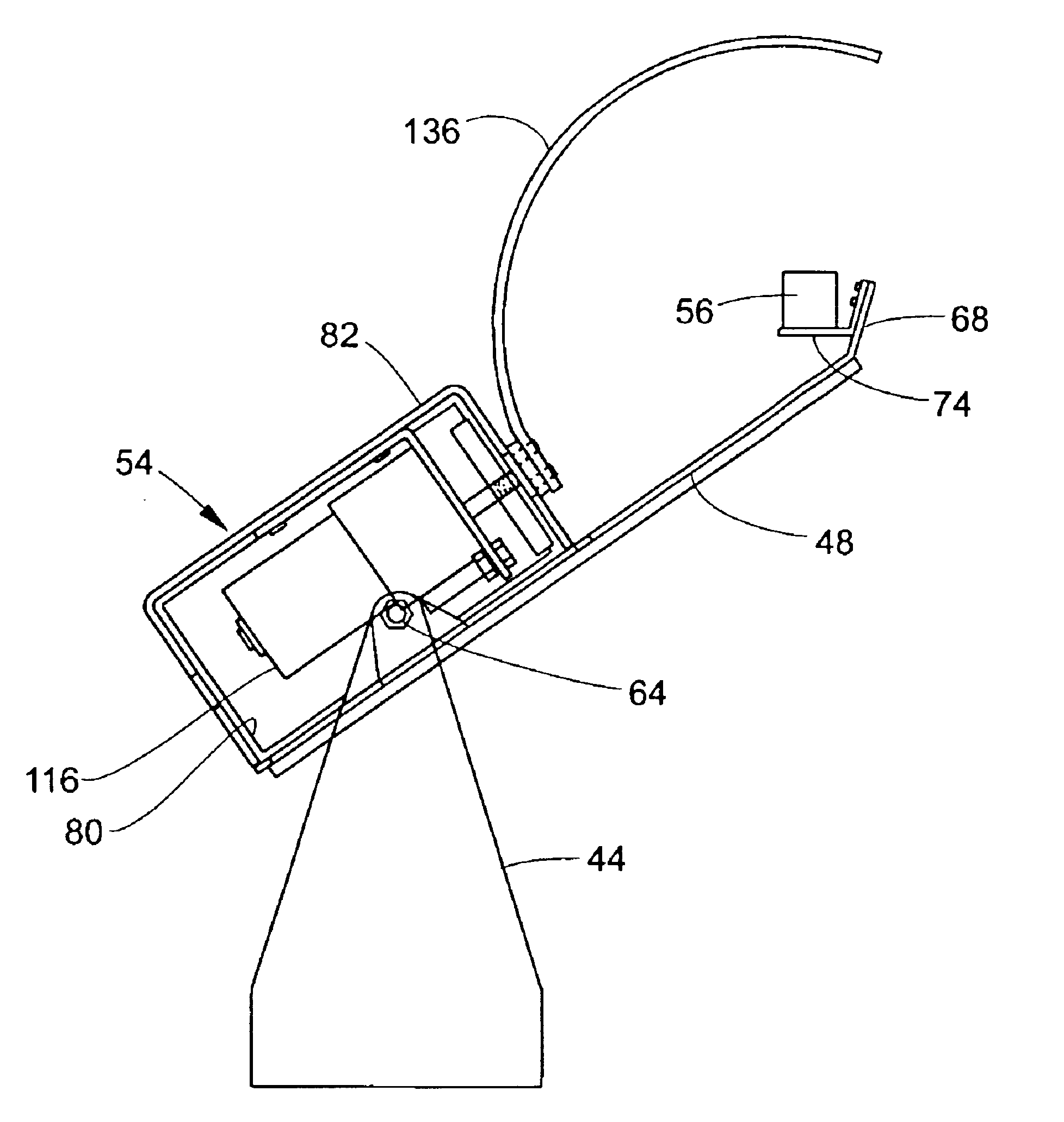
Referring to FIG. 3, a vertical post 40 supports an enclosure 42 that houses a data logger apparatus, a PV controller, and a battery that serves as a power supply for the data logger and the PV controller. The data logger, controller and battery are not shown. The same post supports a U-shaped yoke 44 that in turn supports a PV module 46 and a pyranometer support bracket 48. The crossbar section of the yoke is attached to the post by a connector 50 that permits the yoke to be rotated relative to the post to a selected azimuth position. The PV module is connected to the battery (by wire cable not shown) and serves to generate d. c. power that keeps the battery charged. Bracket 48 serves as a support for a motor housing 54 and a sun light sensor 56.

Referring to FIGS. 4, 6 and 11, bracket 48 is essentially cross-shaped, comprising a pair of laterally-extending arms 58 with upturned ears 60 at their opposite ends. Each ear 60 has a threaded hole 62 for receiving screws 64 that serve to ...


PUM


Abstract

A pyranometer for measuring solar irradiance at a selected site comprises a light detector adapted to produce an output signal in response to incident solar radiation, a reversible motor having a curved shadowband attached to its output shaft, means for mounting the light detector and motor so that the shadowband is at a fixed distance from the light detector; and a motor controller that is adapted to periodically cause the motor to rotate the shadowband from one to the other of two limit positions, with the shadowband acting to momentarily shadow the light detector during its movement between its two limit positions. A datalogger stores and processes the light detector's signal output to provide a measure of total horizontal, direct normal and horizontal diffuse solar irradiance.

Description

FIELD OF THE INVENTIONThis invention relates to apparatus for measuring solar radiation and more particularly to a pyranometer adapted to measure direct normal and horizontal diffuse solar irradiance.BACKGROUND OF THE INVENTIONPhotovoltaic (PV) power is a desirable complement to conventional electric power generation delivery systems. In assessing the value of photovoltaic power generation, electric power planners require solar energy resource data for specific areas where photovoltaic modules are to be installed. Solar energy reaches the earth surface along two paths-irradiance directly from the sun and diffuse irradiance from the sky. Both of those components are required in order to estimate the energy produced by PV systems in a given location. Direct normal and horizontal diffuse solar irradiance data and temperature data are used to estimate the energy produced by fixed and tracking PV systems. Those estimates support utility planning and PV system design studies by comparing ...

Claims


Application Information

Patent Timeline
IPC IPC(8): G01J1/42G01J1/04
CPCG01J1/04G01J1/0403G01J1/42G01J1/0437G01J2001/4266
Inventor LITTLE, RUEL D.
Owner RWE SCHOTT SOLAR
Why Eureka
Try Eureka