Passive entry with anti-theft function
a passive entry and anti-theft technology, applied in anti-theft devices, program control, instruments, etc., can solve the problem that the existing passive entry has the risk of the car door being unlocked using the repeater
- Summary
- Abstract
- Description
- Claims
- Application Information
AI Technical Summary
Benefits of technology
Problems solved by technology
Method used
Image

Examples
first embodiment
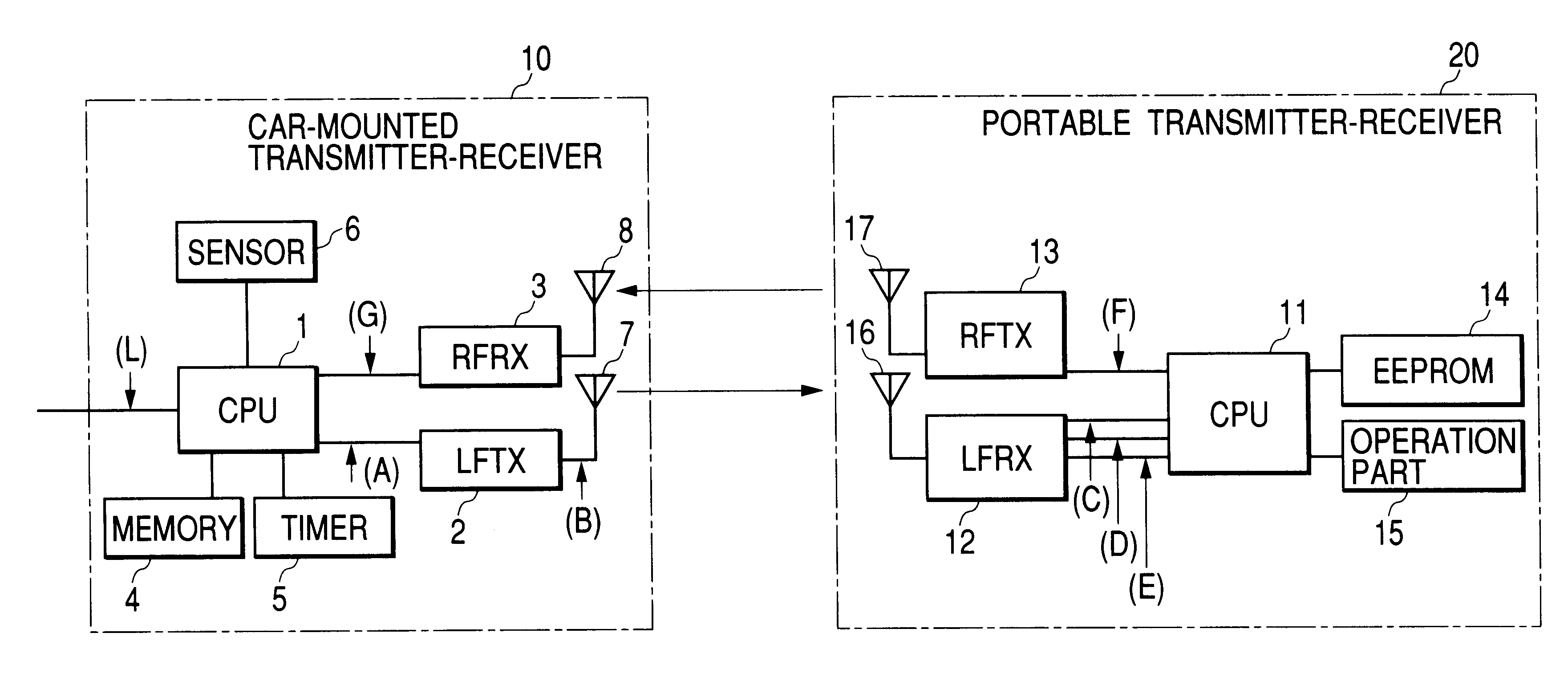
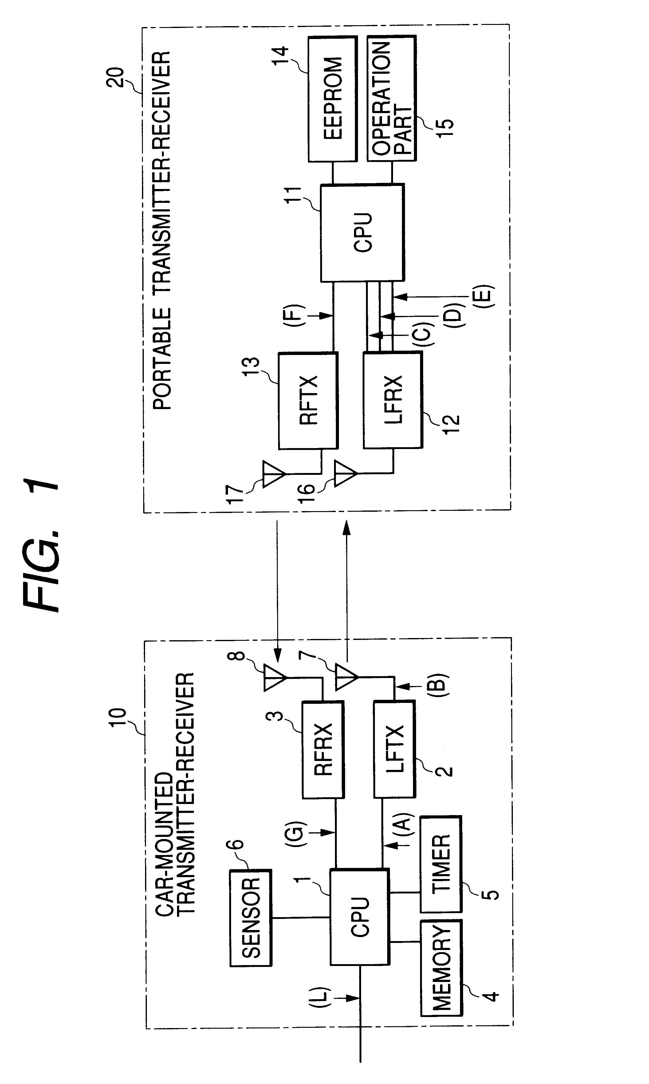
FIG. 1 shows a passive entry having an anti-theft function of the present invention, and is a block diagram showing a configuration of main portions thereof. It shows an example of using one portable transmitter-receiver.
As shown in FIG. 1, a passive entry of the first embodiment comprises a car-mounted transmitter-receiver 10 and a portable transmitter-receiver 20. In this case, the car-mounted transmitter-receiver 10 comprises: a controller (CPU) 1; a low frequency signal transmitter (LFTX) 2; a high frequency signal receiver (RFRX) 3; a storage (memory) 4; a timer 5; a sensor 6; a low frequency transmitting antenna 7; and a high frequency receiving antenna 8. The portable transmitter-receiver 20 comprises: a controller (CPU) 11; a low frequency signal receiver (LFRX) 12; a high frequency signal transmitter (RFTX) 13; a storage 14 composed of EEPROM and the like; an operation part 15; a low frequency receiving antenna 16; and a high frequency transmitting antenna 17.
In the car-mou...
second embodiment
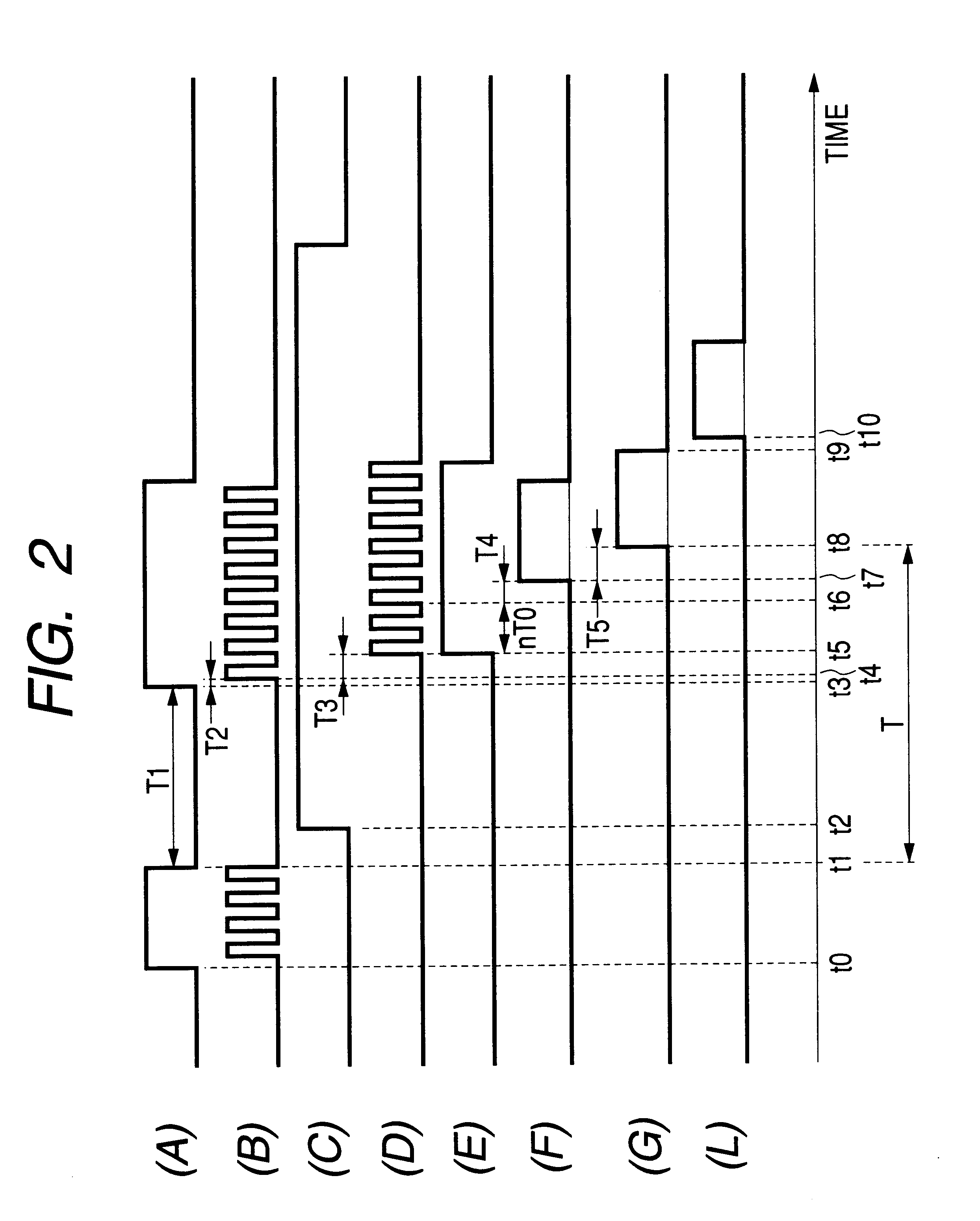
The operation of the passive entry of a second embodiment that has the foregoing configuration will be described with reference to FIG. 4 also.
In the car-mounted transmitter-receiver 10, at time t0, a control signal (wakeup signal) supplied from the controller 1 to the low frequency signal transmitter 2 rises {FIG. 4(A)}, and a low frequency carrier signal is outputted from the low frequency signal transmitter 2 {FIG. 4(B)} and transmitted from the low frequency transmitting antenna 7. Thereafter, upon receiving the low frequency carrier signal through the low frequency receiving antenna 25 in the low frequency signal receiver 21, the first repeater 301 subjects the received low frequency carrier signal to frequency conversion to a high frequency carrier signal in the frequency converting part 23 and transmits the obtained high frequency carrier signal through the high frequency transmitting / receiving antenna 27. Upon receiving the high frequency carrier signal in the high frequency...
PUM
 Abstract
Description
Claims
Application Information
 - Generate Ideas
- Intellectual Property
- Life Sciences
- Materials
- Tech Scout
- Unparalleled Data Quality
- Higher Quality Content
- 60% Fewer Hallucinations
Browse by: Latest US Patents, China's latest patents, Technical Efficacy Thesaurus, Application Domain, Technology Topic, Popular Technical Reports.
© 2025 PatSnap. All rights reserved.Legal|Privacy policy|Modern Slavery Act Transparency Statement|Sitemap|About US| Contact US: help@patsnap.com