Encoding apparatus and encoding method

a technology which is applied in the field of encoding apparatus and encoding method, can solve the problems of reducing the encoding efficiency of quantized coefficients f and the number of bits available, and achieve the effect of improving the encoding efficiency

Inactive Publication Date: 2005-02-01
SONY CORP
View PDF32 Cites 4 Cited by
  • Summary
  • Abstract
  • Description
  • Claims
  • Application Information

AI Technical Summary

Benefits of technology

In view of the above, it is an object of the present invention to provide a technique of improving the encoding efficiency.

Problems solved by technology

Because the total data size of encoded data of a frame is generally fixed, encoding of the gain control number, the gain control position information, and the gain control amount information into such fixed-length codes results in a limitation on the number of bits available for encoding of quantized coefficients F and thus results in a reduction in the encoding efficiency of the quantized coefficients F.

Method used


Image

  • Encoding apparatus and encoding method
  • Encoding apparatus and encoding method
  • Encoding apparatus and encoding method

Examples


Embodiment Construction

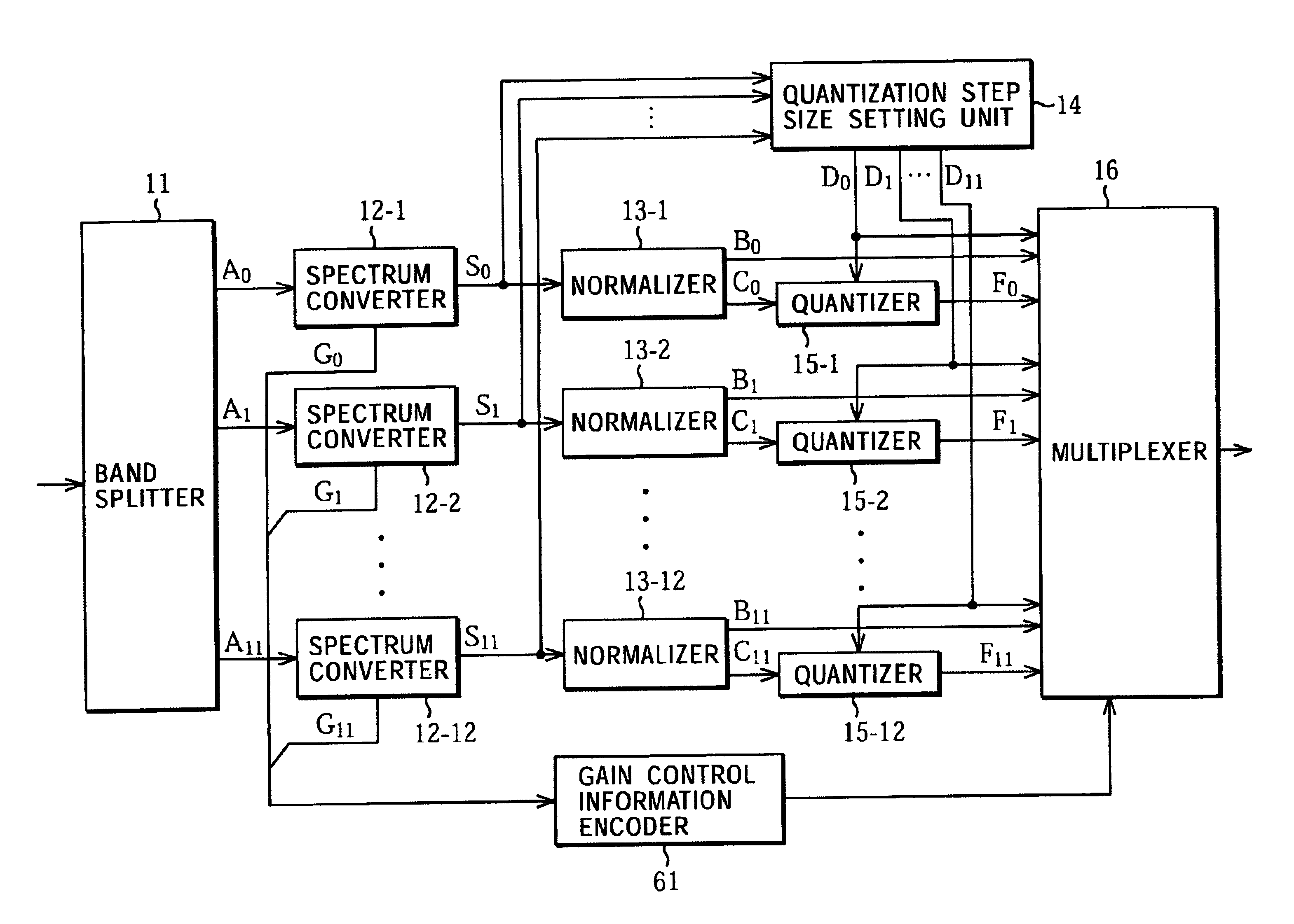
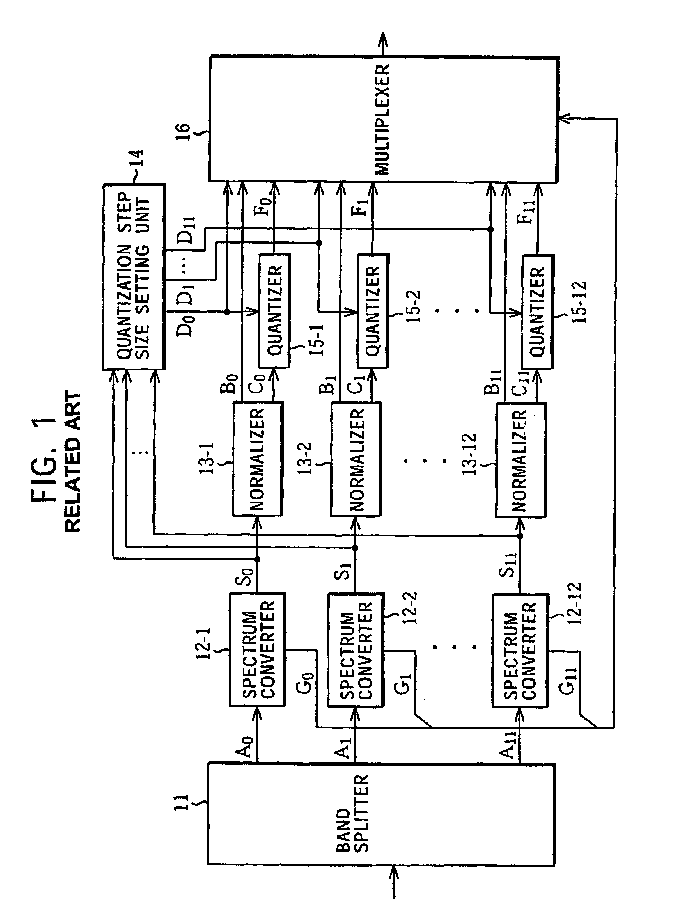
FIG. 7 shows an example of a construction of an encoding apparatus 51 according to the present invention. In addition to the parts employed in the encoding apparatus 1 shown in FIG. 1, the encoding apparatus 51 further includes gain control information encoder 61. The other parts are similar to those of the encoding apparatus 1 shown in FIG. 1 and thus they are not described in further detail herein.

The spectrum converters 12-1 to 12-12 cut encoding units A0 to A11 input from a band splitter 11 into blocks (frames) with a fixed length (time period) and generate gain control information G0 to G11 depending on the amplitudes of the waveform signals in each block. Furthermore, the spectrum converters 12-1 to 12-12 control the gains of the waveform signals in the block in accordance with the gain control information G0 to G11. The spectrum converters 12-1 to 12-12 output produced gain control information G0 to G11 to the gain control information encoder 61.

The spectrum converters 12-1 t...


PUM


Abstract

Information is encoded into a code with a smaller number of bits. An encoding apparatus encodes an acoustic time series signal such that the acoustic time series signal is split into band signals in predetermined bands and gain adjustment is made on the band signals, at a gain control position by a gain control amount, for each of as many positions as indicated by a gain control number. Although the gain control number can take any one of values from 0 to 7, it has a high probability of taking a particular value (0, for example). The gain control number is encoded such that a code with a small number of bits is assigned to the gain control number equal to a value having a high-occurrence probability. The encoding is also applied to a voice recording apparatus.

Description

TECHNICAL FIELDThe present invention relates to an encoding apparatus and an encoding method, and more particularly, to an encoding apparatus and an encoding method capable of performing encoding with an improved encoding efficiency.BACKGROUND ARTFIG. 1 shows an example of a construction of an encoding apparatus 1 according to a conventional technique.A band splitter 11, formed of a filter such as a QMF (Quadrature Mirror Filter) or a PQF (Polyphase Quadrature Filter), splits input audio signal into plural (12, in this specific example) frequency bands and outputs resultant signals of respective bands (hereinafter, such signals will be referred to as encoding units) A0 to A11 (when it is not necessary to distinguish individual encoding units from each other, a simple expression “encoding unit A” will be employed. Similar simple expressions will also be used elsewhere in the present description) to respective spectrum converters 12-1 to 12-12 corresponding to the bands.The band split...

Claims


Application Information

Patent Timeline
Patent Type & Authority Patents(United States)
IPC IPC(8): G10L19/00G10L19/02G10L19/008G10L19/035G10L25/00
CPCG10L19/0204G10L19/032G10L19/0208
Inventor TOYAMA, KEISUKESUZUKI, SHIROTSUJI, MINORU
Owner SONY CORP
Why Eureka
Try Eureka