Method for determining measuring positions and method for planning measuring tracks for measuring an object or a part thereof and device for measuring an object or a part thereof

a technology for measuring tracks and positions, applied in the direction of measurement devices, program control, instruments, etc., can solve the problems of high cost, high precision, and inability to use active measurement using optical sensors, and achieve the effect of high economic efficiency of methods and devices for measuring an object or a part thereof, time efficiency and favorable determination

Inactive Publication Date: 2005-02-01
DAIMLER AG
View PDF19 Cites 14 Cited by
  • Summary
  • Abstract
  • Description
  • Claims
  • Application Information

AI Technical Summary

Benefits of technology

As a general principle, the determination of measuring positions requires a priori knowledge about the object to be measured, for example, the preselection of reference points. These reference points can be provided via a rough measurement of the object to be measured preceding the actual measurement. The triangulation of the reference points yields a second representation of the surface, each surface triangle representing the corresponding part of the surface. The assignment of a measuring position in a position normal to and above the centroid of the triangle guarantees that all marginal regions of the triangle are measured with the same quality. The preselection of a defined distance permits optimum adaptation of the measuring sensor to the measuring task or of the distance to the measuring sensor.
The time efficiency and thus, the economic efficiency of the methods and devices for measuring an object or a part thereof are high because of the favorable determination of the measuring positions and planning of the measuring tracks.

Problems solved by technology

However, active measurement using optical sensors is not yet in use.
This measuring system needs a high-precision and expensive positioning unit and is therefore only used in air-conditioned measuring rooms.

Method used


Image

  • Method for determining measuring positions and method for planning measuring tracks for measuring an object or a part thereof and device for measuring an object or a part thereof
  • Method for determining measuring positions and method for planning measuring tracks for measuring an object or a part thereof and device for measuring an object or a part thereof
  • Method for determining measuring positions and method for planning measuring tracks for measuring an object or a part thereof and device for measuring an object or a part thereof

Examples


Embodiment Construction

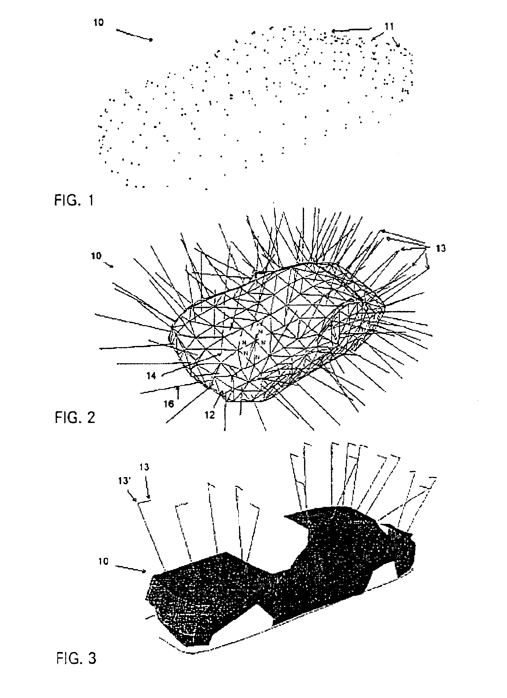
A large object such as a vehicle cannot be measured using the measuring system set forth in the Glaschke article since sufficiently precise positioning systems for measuring spaces of such dimensions are not available at acceptable cost.

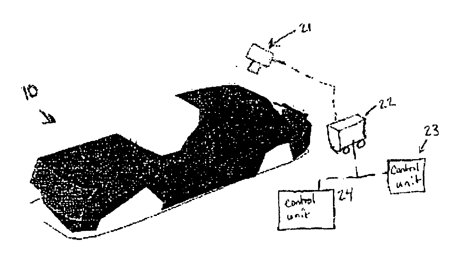
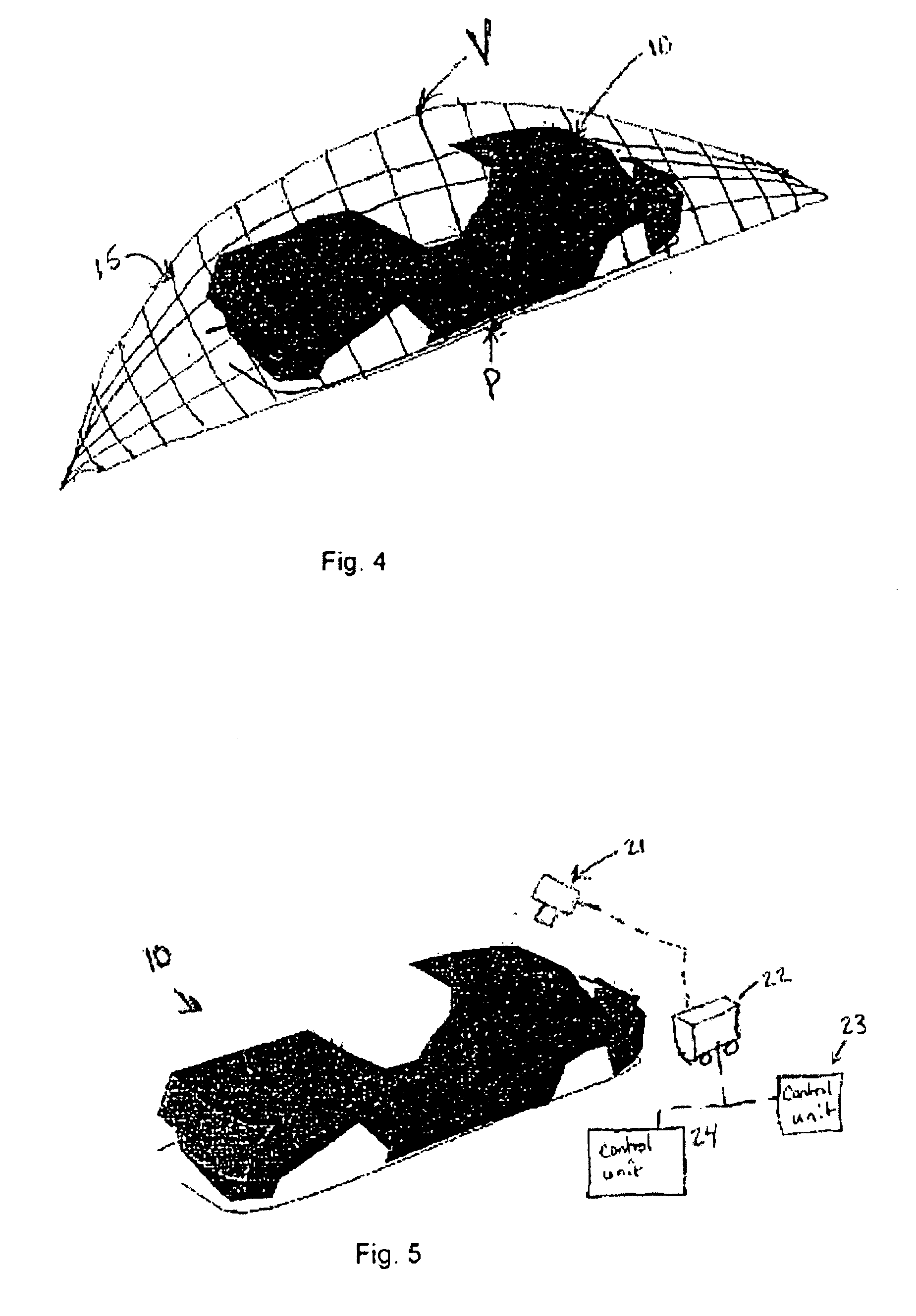
When using measuring marks and a photogrammetric measuring technique and system according to the principle of stripe projection, this limitation of the measuring volume does not apply. A required stripe-projection sensor 21 can be positioned using a mobile robot 22. The robot is composed of a mobile platform having three degrees of freedom and of an arm structure having four degrees of freedom. The redundant degree of freedom with a jib permits the measurement of the engine hood and the roof of the vehicle which would otherwise not be attainable.

In such a system, the used coordinate systems (of the robot 22, of the measuring sensor 21 and of the object 1) can, at the same time, be transformed into each other in a particularly easy manner. This matchi...


PUM


Abstract

A method for determining measuring positions and a method for planning measuring tracks in order to measure an object or a part of an object. Also, a method and a device for measuring an object or a part of an object wherein a triangular surface of an object to be measured is calculated from a plurality of reference points and a measuring position is assigned to each triangle at defined intervals. Said measuring positions are arranged around a support point in a zigzag fashion to form a suitable measuring track. Said measuring track is traversed during the measurement. A device used to determine said measuring positions and to plan said measuring tracks enables the track to be traversed.

Description

BACKGROUNDThe present invention relates to a method for determining measuring positions and to a method for planning measuring tracks as well as to a method for measuring an object or a part thereof, and to a device for measuring an object or a part thereof. A method of that kind for determining measuring positions is already known from Thorsten Glaschke, “Schnelle 3D-Digitalisierung” Fast 3D Digitization], Spektrum No. 74, p. 10, 1999, (the “Glaschke article”). A method of that kind and a device of that kind for measuring an object or a part thereof are already known from the Glaschke article as well.Surface measurement via optical measuring systems, in particular using active vision systems, is gaining more and more importance in industry. For quality assurance and in reverse engineering, tactile 3D coordinate measuring machines have already been used for a long time. Tactile measuring systems offer active measurement strategies for standard measuring tasks (for example, the measu...

Claims


Application Information

Patent Timeline
Patent Type & Authority Patents(United States)
IPC IPC(8): G01B11/00G05B19/00G01B21/20
CPCG01B11/005G05B19/00G01B21/20
Inventor FERBER, STEFANZILKER, ANDREAS
Owner DAIMLER AG
Why Eureka
Try Eureka