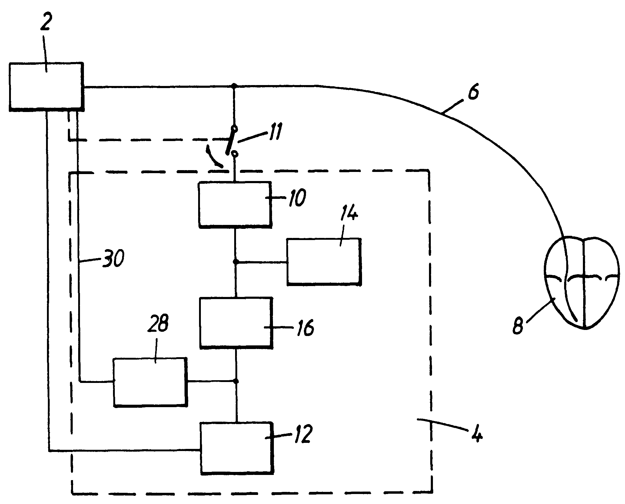
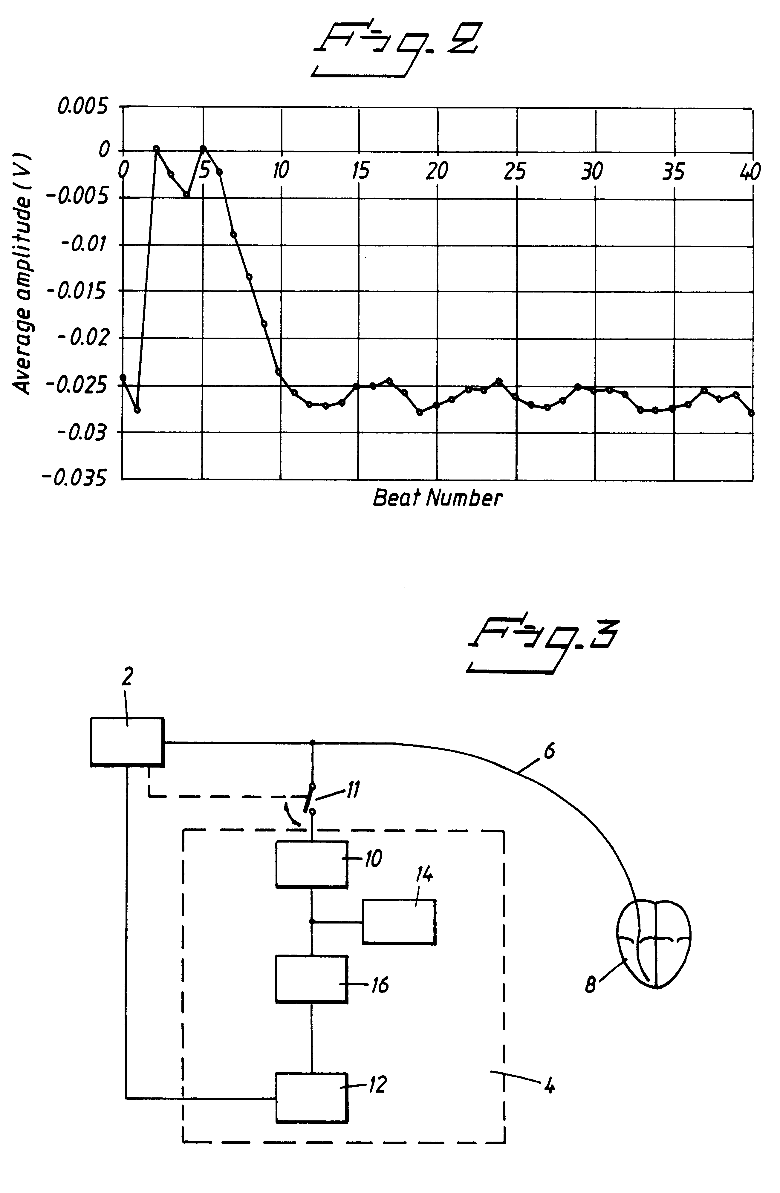
Evoked response detector, averaging the value of the amplitude of the picked-up electrode signal
- Summary
- Abstract
- Description
- Claims
- Application Information
AI Technical Summary
Benefits of technology
Problems solved by technology
Method used
Image
Examples
Embodiment Construction
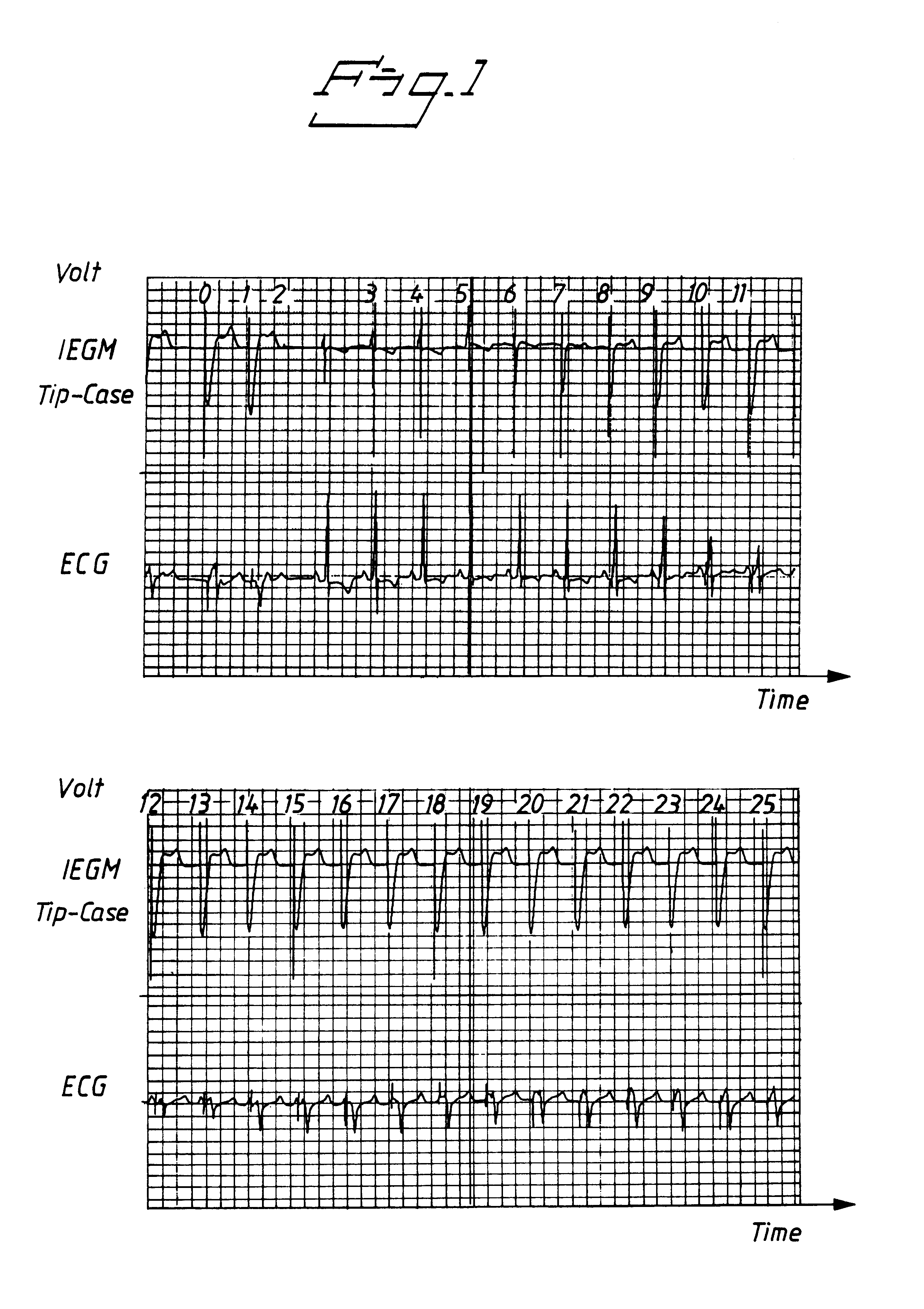
FIG. 1 shows a unipolar IEGM, measured between electrode tip and the casing of the heart stimulator, and the ECG, recorded during experiments on an animal. The recorded heart beats are numbered from 0 to 25.
Beats number 0 and 1 represent two completely stimulated captures.
In the experiments an external pacemaker, operated in VVI mode, was used, but due to the very long blind detection window of approx. 40 msec before the stimulation pulse, the pacemaker has not been inhibited by the intrinsic beats. Accordingly pseudofusion beats have appeared, see beats No. 3, 4, 5, and 6. For these beats stimulation would have been inhibited by a commercially available implantable pacemaker. In the present experiments, however, these beats are interpreted as losses of capture. The sixth beat is the first beat which is somewhat stimulated, but the intrinsic part is much more pronounced than the stimulated one and this beat would probably have been detected by the QRS detector in a commercially avai...
PUM
 Abstract
Description
Claims
Application Information
 - R&D
- Intellectual Property
- Life Sciences
- Materials
- Tech Scout
- Unparalleled Data Quality
- Higher Quality Content
- 60% Fewer Hallucinations
Browse by: Latest US Patents, China's latest patents, Technical Efficacy Thesaurus, Application Domain, Technology Topic, Popular Technical Reports.
© 2025 PatSnap. All rights reserved.Legal|Privacy policy|Modern Slavery Act Transparency Statement|Sitemap|About US| Contact US: help@patsnap.com


