
Adaptive retry mechanism

a retry mechanism and bus interface technology, applied in the field of bus interfaces, can solve problems such as increasing the latency of a particular transaction, and achieve the effect of efficient bus bandwidth us

Inactive Publication Date: 2005-02-01
AVAGO TECH INT SALES PTE LTD
View PDF8 Cites 11 Cited by
  • Summary
  • Abstract
  • Description
  • Claims
  • Application Information

AI Technical Summary

Benefits of technology

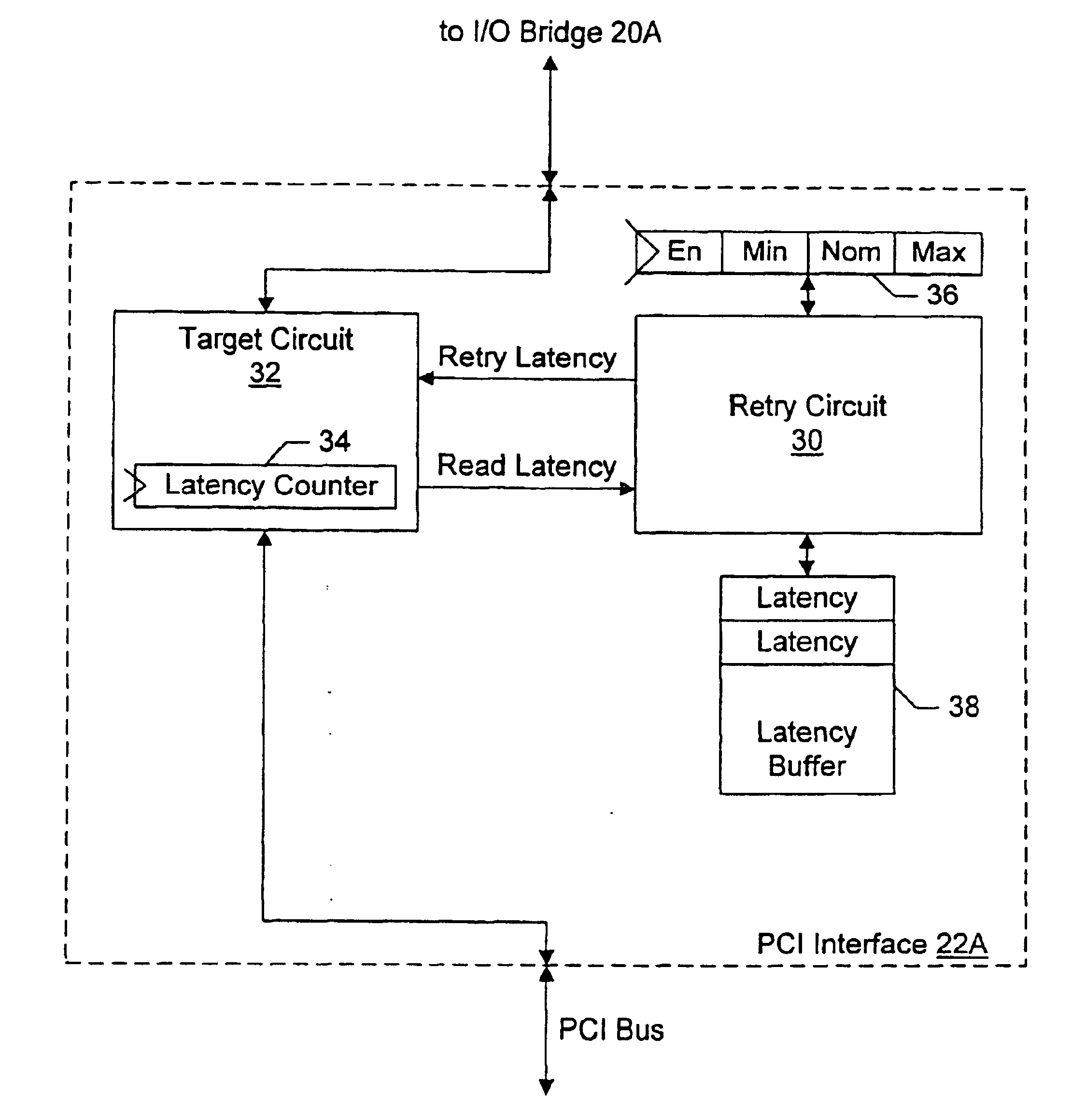
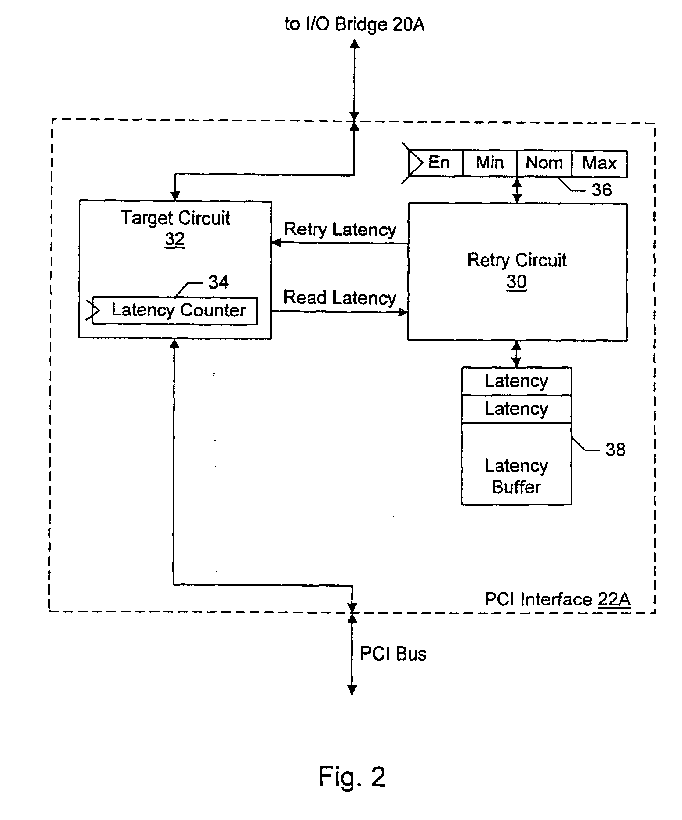
The problems outlined above are in large part solved by an adaptive retry mechanism described herein. The mechanism may record latencies of recent transactions (e.g. the first data transfer latency), and may select a retry latency from two or more retry latencies. The retry latency may be used for a transaction, and may specify a point in time during the transaction at which the transaction is retried if the first data transfer has not yet occurred. Since the selected retry latency is based on the latencies currently being experienced in the system, the retry latency may be dynamically adjusted to more efficiently use bus bandwidth. In one embodiment, the mechanism may be used on the PCI bus although any bus which allows for retry of transactions may employ the mechanism.
The recorded latencies may be measured directly during the recent transactions, or the latencies may be calculated or estimated from multiple internal states of the system. For example, in one embodiment, the latencies may be calculated based on the memory controller's memory read latency, the number of transactions queued in the memory controller, and the amount of traffic on the system bus. The number of transactions queued in the memory controller may increase the latency for a particular transaction since some or all of the queued transactions may be performed by the memory controller prior to the particular transaction. The amount of traffic on the system bus may increase the latency for a particular transaction by delaying access to the bus in response to the particular transaction.
In one implementation, the set of retry latencies includes a minimum retry latency, a nominal retry latency, and a maximum retry latency. The nominal retry latency may be set slightly greater than the expected latency of transactions in the system. The minimum retry latency may be less than the nominal retry latency and the maximum retry latency may be greater than the nominal retry latency. If latencies greater than the nominal retry latency but less than the maximum retry latency are being experienced, the maximum retry latency may be selected, thus avoiding retrying transactions just before the data arrives. On the other hand, if latencies greater than the maximum retry latency are being experienced, the minimum retry latency may be selected, thus more rapidly retrying transactions and therefore freeing bus bandwidth for other transactions.

Problems solved by technology

The amount of traffic on the system bus may increase the latency for a particular transaction by delaying access to the bus in response to the particular transaction.

Method used


Image

  • Adaptive retry mechanism
  • Adaptive retry mechanism
  • Adaptive retry mechanism

Examples


Embodiment Construction

System Overview

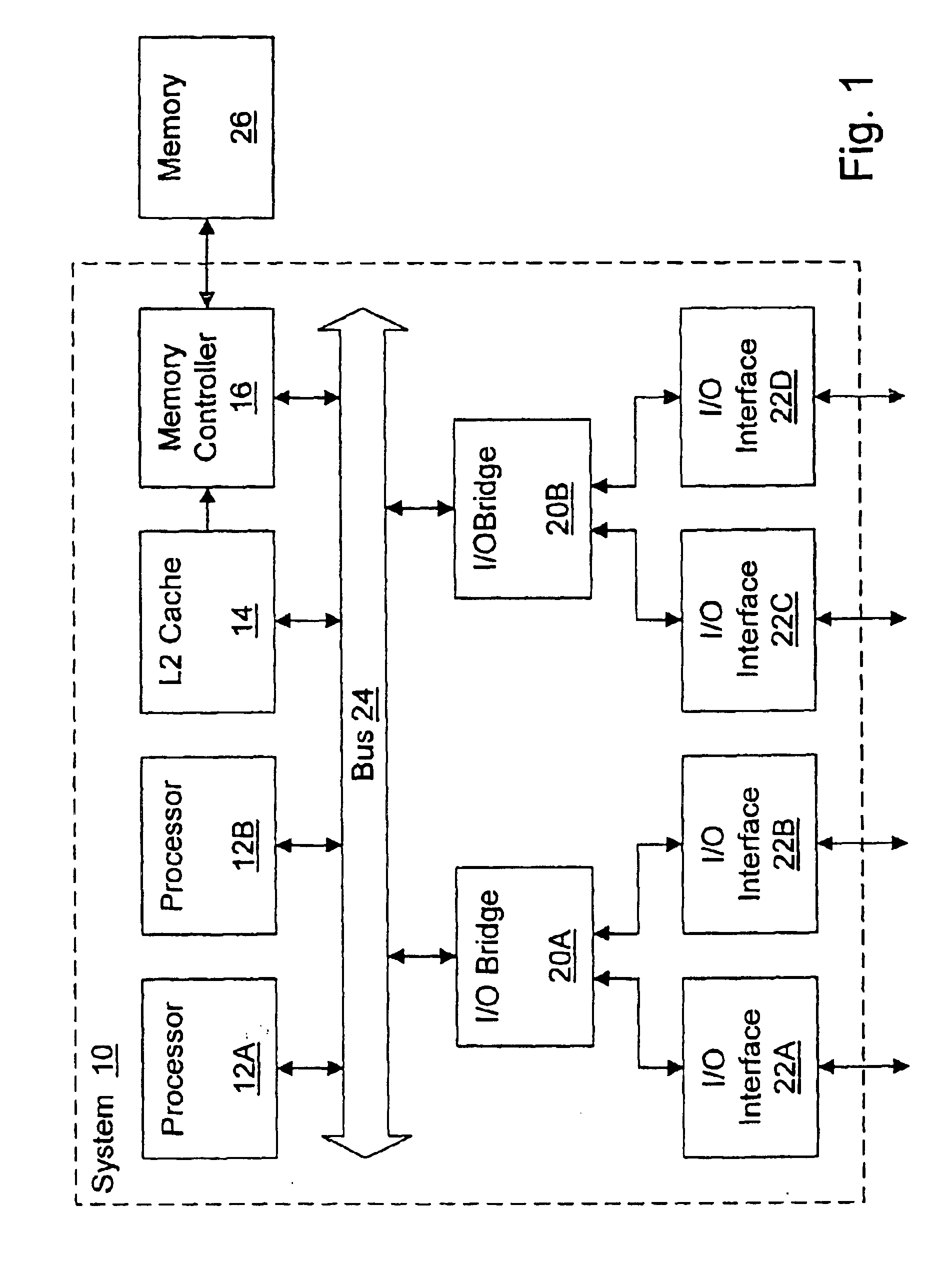
Turning now to FIG. 1, a block diagram of one embodiment of a system 10 is shown. Other embodiments are possible and contemplated. In the embodiment of FIG. 1, system 10 includes processors 12A-12B, an L2 cache 14, a memory controller 16, a pair of input / output (I / O) bridges 20A-20B, and I / O interfaces 22A-22D. System 10 may include a bus 24 for interconnecting the various components of system 10. As illustrated in FIG. 1, each of processors 12A-12B, L2 cache 14, memory controller 16, and I / O bridges 20A-20B are coupled to bus 24. Thus, each of processors 12A-12B, L2 cache 14, memory controller 16, and I / O bridges 20A-20B may be an agent on bus 24 for the illustrated embodiment. I / O bridge 20A is coupled to I / O interfaces 22A-22B, and I / O bridge 20B is coupled to I / O interfaces 22C-22D. L2 cache 14 is coupled to memory controller 16, which is further coupled to a memory 26.

Processors 12A-12B may be designed to any instruction set architecture, and may execute programs...


PUM


Abstract

An adaptive retry mechanism may record latencies of recent transactions (e.g. the first data transfer latency), and may select a retry latency from two or more retry latencies. The retry latency may be used for a transaction, and may specify a point in time during the transaction at which the transaction is retried if the first data transfer has not yet occurred. In one implementation, the set of retry latencies includes a minimum retry latency, a nominal retry latency, and a maximum retry latency. The nominal retry latency may be set slightly greater than the expected latency of transactions in the system. The minimum retry latency may be less than the nominal retry latency and the maximum retry latency may be greater than the nominal retry latency. If latencies greater than the nominal retry latency but less than the maximum retry latency are being experienced, the maximum retry latency may be selected. On the other hand, if latencies greater than the maximum retry latency are being experienced, the minimum retry latency may be selected.

Description

BACKGROUND OF THE INVENTION1. Field of the InventionThis invention is related to the field of bus interfaces, and more particularly, to retry mechanisms in bus interfaces.2. Description of the Related ArtGenerally, devices in a system may use a bus to communicate. Particularly, it is frequent that a variety of peripheral devices are coupled to a bus (e.g. the Peripheral Component Interconnect bus, or PCI bus) for communicating with other devices (either directly connected to the bus or indirectly through one or more bus bridges). The bus is a shared resource among the devices coupled to the bus, and thus efficient use of the bandwidth available on the bus may be important to overall system performance. During the time that a transaction is active on the bus, other transactions may be precluded from being initiated or completing. For example, the PCI bus is a shared address / data bus in which the address and data are transferred on the same lines (but at different times). A transactio...

Claims


Application Information

Patent Timeline
IPC IPC(8): G06F13/00G06F13/36G06F13/14G06F13/16
CPCG06F13/161
Inventor KELLER, JAMES B.NING, CHUN H.CHUI, KWONG-TAK A.HAYTER, MARK D.
Owner AVAGO TECH INT SALES PTE LTD
Learn More