Method and apparatus for determining flow velocity in a channel

a flow velocity and channel technology, applied in the field of ultrasonic flowmeters, can solve the problems of gaussian integration methods with bias uncertainties of up to 3%, integration methods with bias uncertainties of up to 1%, and complex problems for flow-metering engineers, etc., and achieve the effect of any accuracy degradation

Inactive Publication Date: 2005-02-08
SAVANT MEASUREMENT CORP
View PDF46 Cites 27 Cited by
  • Summary
  • Abstract
  • Description
  • Claims
  • Application Information

AI Technical Summary

Benefits of technology

A further advantage of the present invention is that the combination of isolating flow conditioner technology with ultrasonic flowmeter technology enables a self-diagnostic capabilities for measuring the “real time” health of the flowmeter. A one-path design provides a low-level capability for measuring flowmeter health, while multi-path designs provide a high-level capab

Problems solved by technology

However, in the industrial environment, multiple piping configurations assembled in series generate complex problems for flow-metering engineers.
Based on available public research, Gaussian integration methods have a bias uncertainty of up to 3% due to variations in piping configuration.
According to available literature, this integration method has an additional bias uncertainty of up to 1% due to variations in piping configuration.
No bias uncertainty information is

Method used


Image

  • Method and apparatus for determining flow velocity in a channel
  • Method and apparatus for determining flow velocity in a channel
  • Method and apparatus for determining flow velocity in a channel

Examples


Embodiment Construction

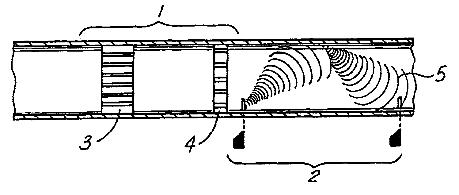
Referring now to FIGS. 3 and 4, the present invention combines an isolating flow conditioner section 1 with an ultrasonic flowmeter section 2. The isolating flow conditioner section 1 of the present invention eliminates swirl (defined as reducing swirl or the ratio of radial velocity to axial velocity to less than 2 degrees) and eliminates asymmetry (defined as less than 5% difference in flow velocity between parallel chords on opposing sides of the flow centerline) upstream of the ultrasonic meter section 2. In the preferred embodiment, the isolating flow conditioner section 1 consists of an anti-swirl device 3 followed by a profile device 4 as shown in FIGS. 3 and 4. However, the isolating flow conditioner section 1 could also consists of various combinations of other devices, such as nozzles, contractions, anti-swirl devices, profile devices, and static mixers. The important parameter for any combination is the elimination of swirl and the achievement of axisymmetrical flow (both...


PUM


Abstract

An ultrasonic flowmeter for measuring fluid flow are disclosed. The invention combines isolating conditioner technology with ultrasonic technology to determine flow velocity. The method and apparatus of the invention does not require the use of integration techniques or the prior determination of flow swirl or asymmetry to achieve accuracy. The performance of this novel flowmeter exceeds the performance of current ultrasonic flowmeters by an order of four to twelve times and offers significant savings in manufacturing and maintenance costs. The disclosed flowmeter also has self-diagnostic capabilities.

Description

BACKGROUND OF THE INVENTION1. Field of the InventionThe invention relates to the field of ultrasonic flowmeters and, in particular, to an ultrasonic flowmeter that combines flow conditioning technology with simple and inexpensive ultrasonic technology to yield high accuracy. The method and apparatus of the invention does not require the use of integration techniques or the prior determination of flow swirl or asymmetry to achieve accuracy. The invention also allows implementation of various self-diagnostic features.2. Description of the Prior ArtReferring now to FIG. 1, flowmeters are generally classified as either energy additive or energy extractive. Energy additive meters introduce energy into the flowing stream to determine flowrate. Common examples of energy additive meters are magnetic meters and ultrasonic meters. Energy extractive meters require energy from the flowing stream, usually in the form of pressure drop, to determine the fluid's flowrate. Examples of energy extract...

Claims


Application Information

Patent Timeline
IPC IPC(8): G01F1/66
CPCG01F1/662
Inventor GALLAGHER, JAMES E.
Owner SAVANT MEASUREMENT CORP
Why Eureka
Try Eureka