Direct acting gas regulator

a gas regulator and direct-acting technology, applied in fluid pressure control, process and machine control, instruments, etc., can solve the problems of large pressure regulators, inconvenient operation, and easy to damage, and achieve high accuracy, low cost, and low cost

Inactive Publication Date: 2005-02-08
PRESSURE SPECIALIST
View PDF34 Cites 62 Cited by
  • Summary
  • Abstract
  • Description
  • Claims
  • Application Information

AI Technical Summary

Benefits of technology

A direct acting pressure regulator controls the flow of a gas from a high pressure source to a low pressure device. Gas is delivered from the regulator at a predetermined outlet pressure. The present regulator provides a low cost, highly accurate pressure regulating device that is sufficiently small and light-weight so that it does not increase, to any extent, the weight carried by a participant in a paint ball sporting event.

Problems solved by technology

The dangers of explosives include not only the physical danger of the explosion but also the increased speed that such explosions impart to projectiles, potentially making innocuous projectiles, such as paintballs, deadly.
Although high-pressure gas is needed at the gun firing mechanism to propel the paint balls, typically the pressure in these bottles is greater than the pressure needed to safely propel the projectile within the parameters of the game.
Known pressure regulator can be quite large and as such can add considerable weight to the gun.
In that one of the objectives of paint ball is to avoid one's opponent, any added weight is undesirable.
In addition, such large, highly machined regulators can be quite costly.
Moreover, although many such regulators in fact function well to regulate and reduce pressure from the bottle to the firing mechanism, often such pressure regulation or reduction is rough.

Method used


Image

  • Direct acting gas regulator
  • Direct acting gas regulator
  • Direct acting gas regulator

Examples


Embodiment Construction

While the present invention is susceptible of embodiment in various forms, there is shown in the drawings and will hereinafter be described a presently preferred embodiment with the understanding that the present disclosure is to be considered an exemplification of the invention and is not intended to limit the invention to the specific embodiment illustrated.

It should be further understood that the title of this section of this specification, namely, “Detailed Description Of The Invention”, relates to a requirement of the United States Patent Office, and does not imply, nor should be inferred to limit the subject matter disclosed herein.

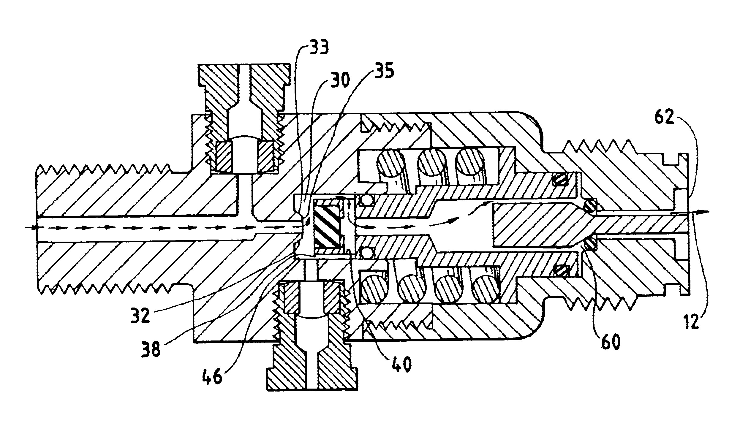
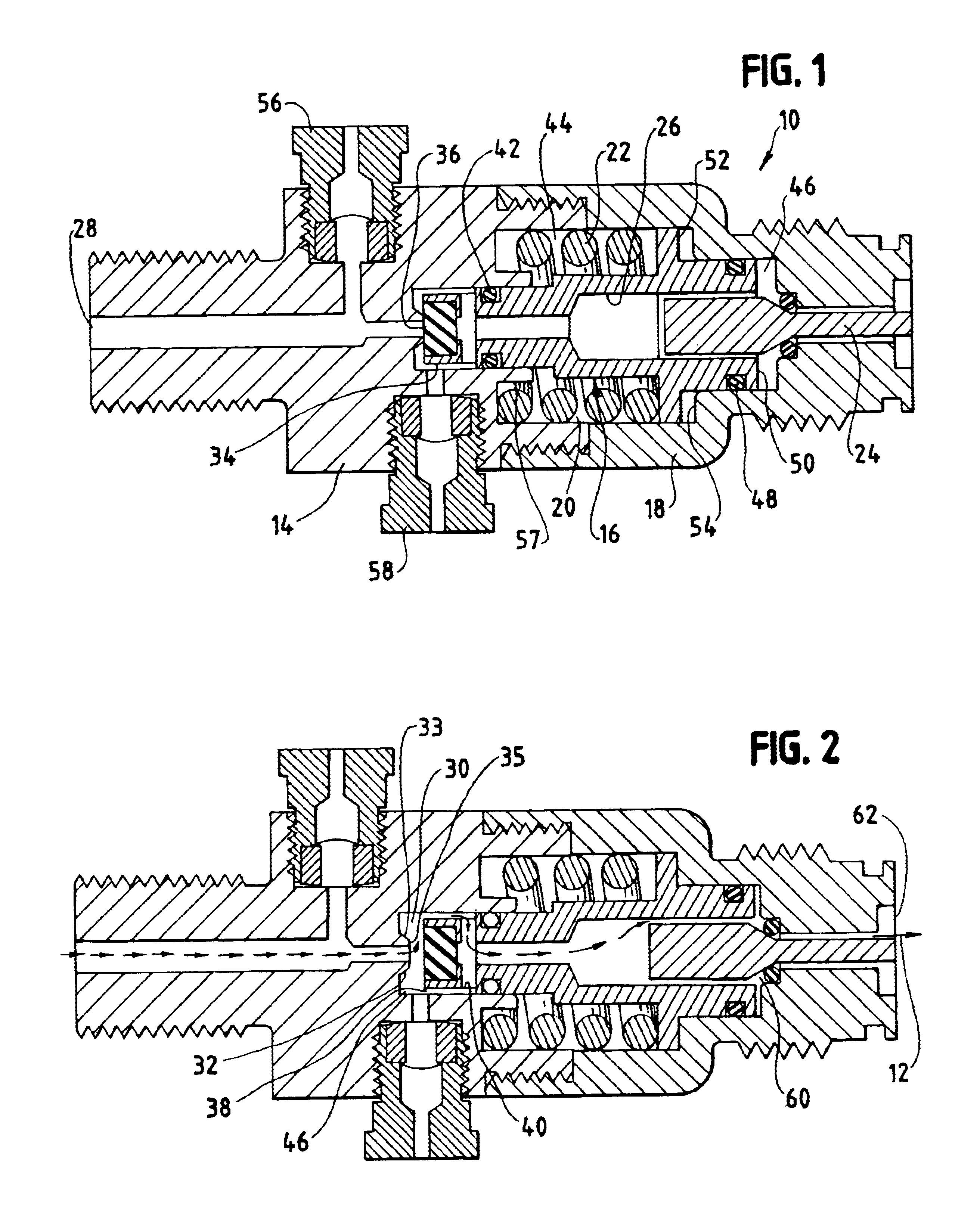
Referring to the figures and briefly to FIG. 2, a present regulator is shown in the open condition such that a regulated flow path, indicated generally at 12, is provided from a high pressure gas source to a downstream device such as a paint ball gun or the like. The controlled downstream pressure is regulated essentially regardless of the higher up...


PUM


Abstract

A direct acting pressure regulator controls the flow of a gas from a high pressure source to a low pressure device. Gas is delivered from the regulator at a predetermined outlet pressure. The regulator includes a body having a high pressure inlet and defining a seat. A bonnet is engageable with the body to define a piston chamber within the body and the bonnet. The bonnet has a regulated gas outlet. A piston is disposed within the piston chamber and defines a gap between the piston and a wall defining the chamber. The piston is movable between an open regulator condition and a closed regulator condition. The piston includes a plug having a sealing surface engageable with the seat and movable toward the seat to the closed regulator condition and away from the seat to the open regulator condition. The plug includes axially disposed openings therein for communicating gas from around the plug to a central longitudinal bore in the piston. The piston has an impingement surface in flow communication with the central bore such that gas pressure on the impingement surface exerts a force on the piston to move the piston to the closed regulator condition. A spring urges the piston to the open regulator condition.

Description

BACKGROUND OF THE INVENTIONThe present invention is directed to a novel pressure regulator. More particularly, the present invention relates to a linear, direct acting pressure regulator for use in paint ball guns that use compressed gas to fire projectiles. The present invention is also adapted for use with other pressurized gas devices.Sporting events that provide the participant with an adventure in military strategy and the feel of the fear and exhilaration of battle have become very popular. Generally participants are equipped with a gas projectile gun or rifle (which can launch a projectile without seriously harming the victim) and protective gear and are divided into two or more combat groups each with the goal of surviving the others.One such sporting event is commonly referred to as “paintball”. In this event, participants fire paint-filled projectile balls at one another. In a typical paintball event, participants fire projectiles, or paintballs, at one another and, when s...

Claims


Application Information

Patent Timeline
Patent Type & Authority Patents(United States)
IPC IPC(8): G05D16/10G05D16/04
CPCG05D16/103Y10T137/87917Y10T137/7808Y10T137/7811
Inventor CARROLL, KENT L.
Owner PRESSURE SPECIALIST
Why Eureka
Try Eureka