Industrial multilayer fabric

a multi-layer fabric and fabric technology, applied in the field of industrial fabrics, can solve the problems inability to obtain the and inability to use yarns with excessively large wire diameters, and achieve the effect of deteriorating water filtering properties, superior surface properties and knotting force, and preferable effect of paper-manufacturing fabrics

Inactive Publication Date: 2005-02-08
NIPPON FILCON
View PDF5 Cites 11 Cited by
  • Summary
  • Abstract
  • Description
  • Claims
  • Application Information

AI Technical Summary

Benefits of technology

There is provided a multilayer fabric in which the surface of the upper surface side layer is formed between upper surface side warps and a warp ground yarn knotting yarn for connecting the upper surface side layer to the running surface side layer is disposed, and which is superior in the surface property and knotting force. When a ground yarn is used as the knotting yarn, and when the knotting yarn moves downwards to a lower surface side of the fabric of the running surface side layer, and the ground yarn does not appear on the upper surface side layer, the plain weave texture is not formed, and therefore a pair of knotting yarns have to be used. However, when the pair of knotting yarns are disposed in the upper surface side warp, the water filtering property is deteriorated, and a preferable effect of a paper-manufacturing fabric cannot be obtained.

Problems solved by technology

However, when the pair of knotting yarns are disposed in the upper surface side warp, the water filtering property is deteriorated, and a preferable effect of a paper-manufacturing fabric cannot be obtained.
Since a portion of the knotting yarn appears on the surface of the upper surface side layer in order to connect two layers to each other, a yarn having an excessively large wire diameter cannot be used.
On the other hand, a knotting yarn having a small wire diameter and little strength cannot strongly connect the layers.
Therefore, problems sometimes arise that the knotting yarn extends under an applied tension, the knotting yarn tossed between the upper surface side fabric and running surface side fabric generates an internal friction, and that a gap is generated in the fabric or the fabric is separated.
Moreover, a method of disposing a large number of knotting yarns to enhance the knotting force has also been proposed, but the method has problems that the a water filtering space is narrowed by the presence of the knotting yarn and the water filtering property is adversely influenced, and that the knotting yarn for connecting two fabrics to each other is entangled with a yarn on the upper surface side, drags the yarn by the knotting force, therefore forms a dent in the surface of the upper surface side layer, and deteriorates the surface property of the fabric.

Method used


Image

  • Industrial multilayer fabric
  • Industrial multilayer fabric
  • Industrial multilayer fabric

Examples


examples

The present invention will be described based on embodiments with reference to the drawings.

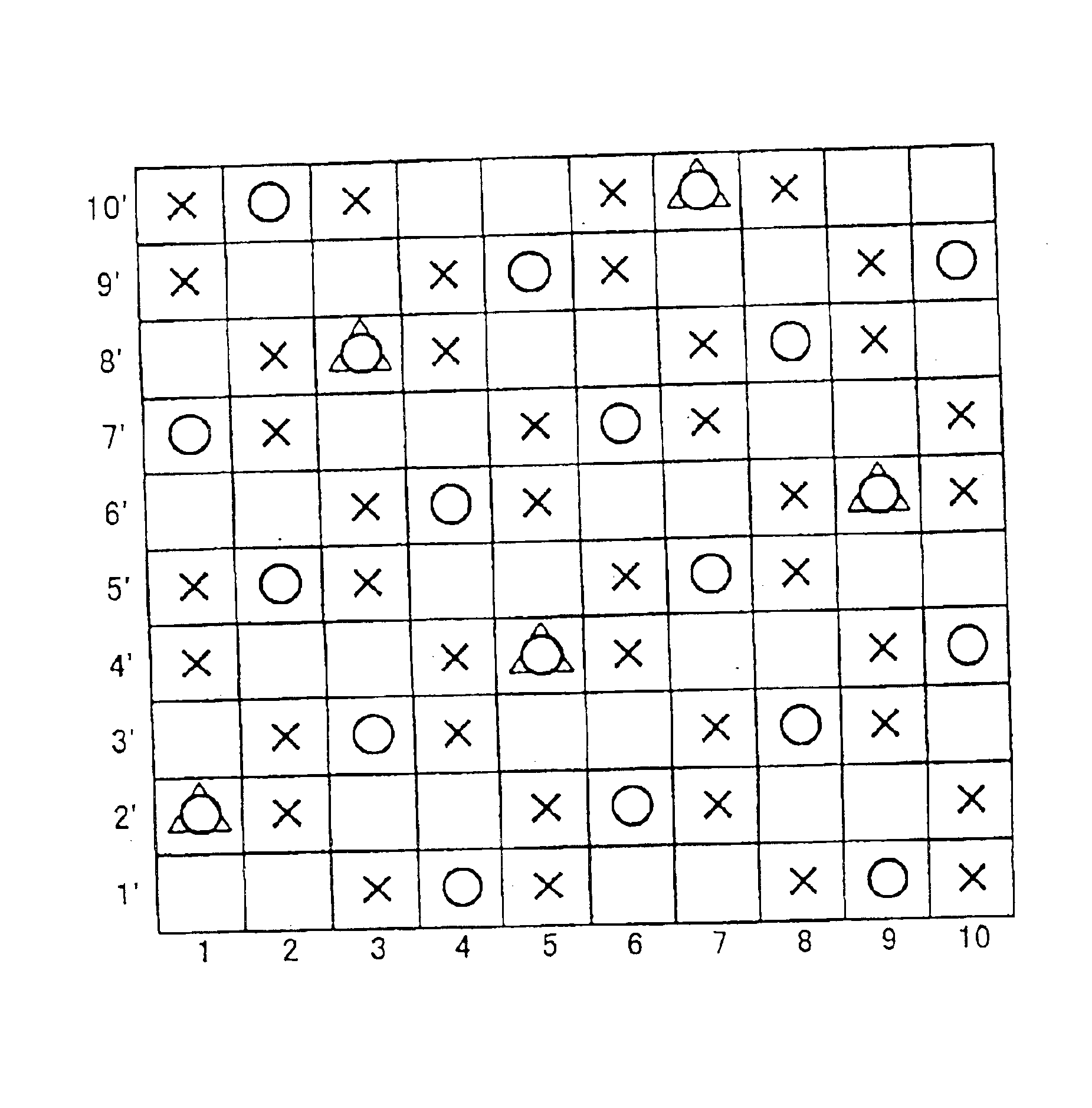
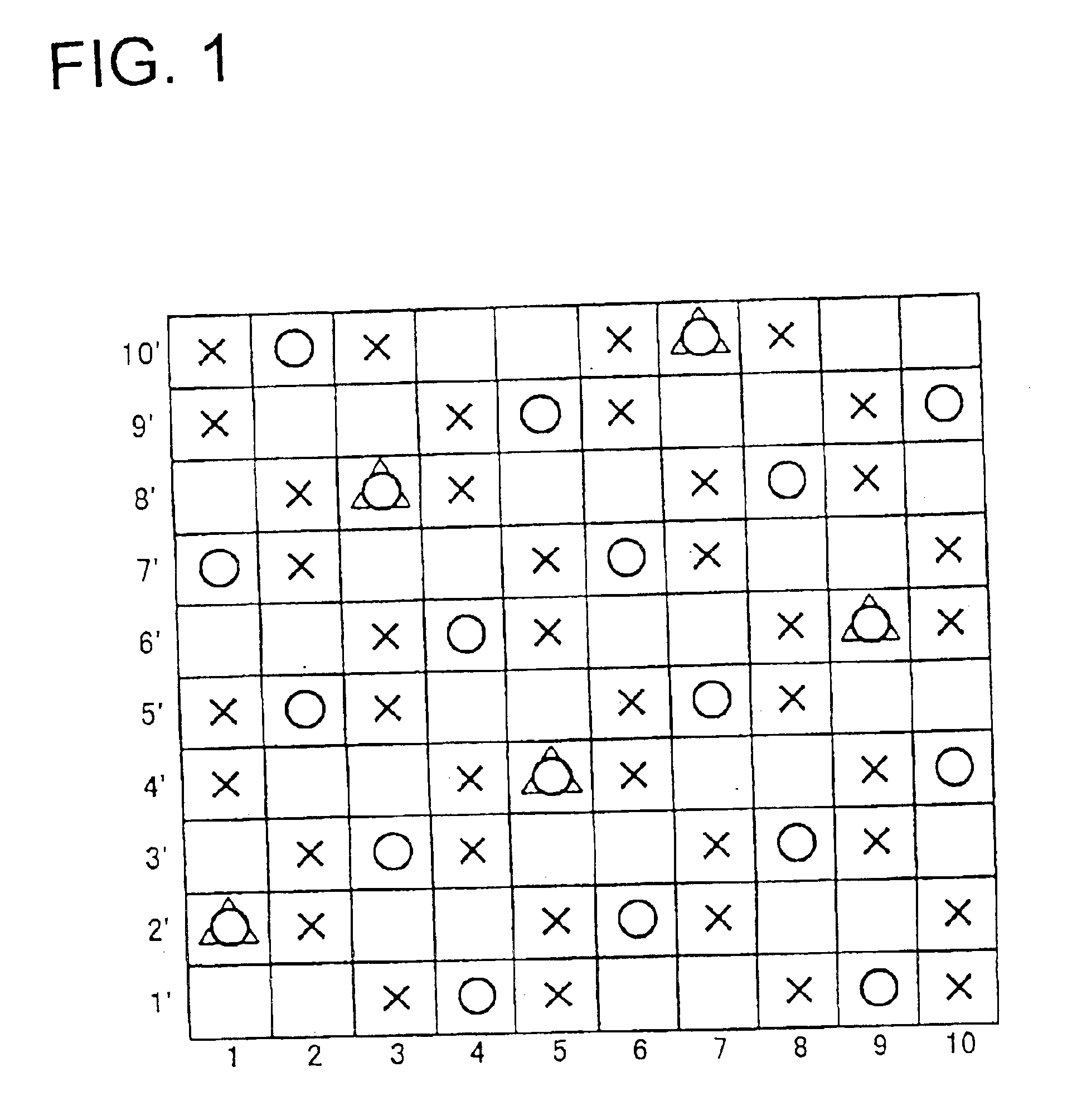
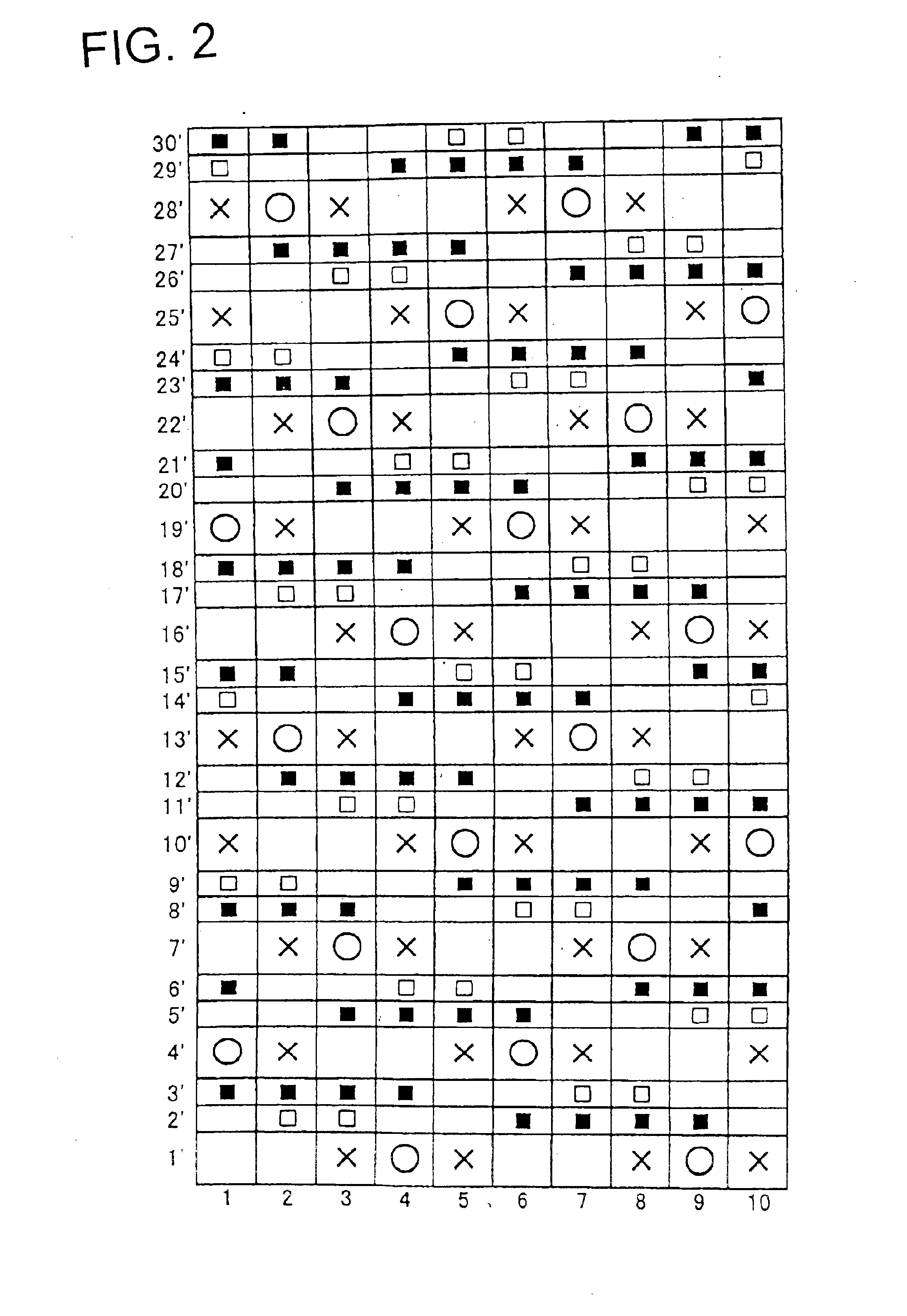
FIGS. 1, 2, 3 are design diagrams showing a complete texture of a repeating unit according to the embodiments of the present invention.

FIG. 1 shows the embodiment of the present invention, and one of examples in which a warp ground yarn knotting yarn is used in a ground yarn knotting yarn. FIG. 2 shows another embodiment of the present invention, and one of examples in which an auxiliary weft knotting yarn is used in the ground yarn knotting yarn. FIG. 3 shows another embodiment of the present invention and shows one of examples in which both the warp ground yarn knotting yarn and the auxiliary weft knotting yarn are used in the ground yarn knotting yarn.

The complete texture is a minimum repeated unit of a fabric texture, and the complete textures are vertically and horizontally connected to one another to form the overall texture of a fabric.

In the design diagrams of FIGS. 1 to 3, a warp and...

embodiment 1

In the design diagram of FIG. 1, reference numerals 1, 2, 3, 4, 5, 6, 7, 8, 9, 10 denote yarns of a warp direction, and the upper surface side and running surface side warps, and the warp ground yarn knotting yarn and running surface side warp are vertically disposed. The running surface side warps are disposed in all of the yarns 1 to 10, the upper surface side warps are disposed on the yarns of even numerals 2, 4, 6, 8, 10, and the warp ground yarn knotting yarns are disposed on the yarns of odd numerals 1, 3, 5, 7, 9.

Reference numerals 1′, 2′, 3′, 4′, 5′, 6′, 7′, 8′, 9′, 10′ denote wefts, and the upper surface side wefts are vertically disposed on the running surface side weft.

The surface of the upper surface side layer has a texture in which the upper surface side warp passes over two continuous upper surface side wefts and then passes under three upper surface side wefts, and the texture is repeated twice in one cycle. The warp ground yarn knotting yarn passes over two upper su...

embodiment 2

FIG. 2 shows an embodiment in which an auxiliary weft knotting yarn of the present invention is used.

An auxiliary weft is a yarn which corrects dents in an original weft, and between the wefts disposed between the original wefts, and this produces an effect that a surface property is remarkably improved.

In the design diagram of FIG. 2, reference numerals 1, 2, 3, 4, 5, 6, 7, 8, 9, 10 denote warps, and the upper surface side and running surface side warps are vertically disposed. Yarns of a weft direction are denoted with 1′, 2′, 3′ . . . 29′, 30′, among these, the wefts are 1′, 4′, 7′, 10′, 13′, 16′, 19′, 22′, 25′, 28′, the upper surface side wefts are disposed on the upper side, and the running surface side wefts are disposed on the lower side. Moreover, the other yarns are auxiliary weft knotting yarns, and pairs of 2′ and 3′, 5′ and 6′, 8′ and 9′, 11′ and 12′, 14′ and 15′, 17′ and 18′, 20′ and 21′, 23′ and 24′, 26′ and 27′, and 29′ and 30′ are disposed.

The textures of the upper s...


PUM


Abstract

An industrial multilayer fabric has at least an upper surface side layer and running surface side layer. The upper surface side layer and running surface side layer are connected by a ground yarn knotting yarn which forms a portion of the surface of the upper surface side layer. An upper surface side warp which appears on the surface of the upper surface side layer passes over two continuous upper surface side wefts and the ground yarn knotting yarn, and then passes under three continuous upper surface side wefts.

Description

BACKGROUND OF THE INVENTIONThe present invention relates to industrial fabrics such as a papering fabric, a conveying belt, and a filter cloth.A fabric woven with warps and wefts has heretofore been used as an industrial fabric, and used broadly in many fields such as a papering wire, conveying belt, and filter cloth, and fabric properties suitable for uses and use environments have been required. Requirements especially in the papering wire for use in a paper-manufacturing process in which meshes of the fabric are used to dehydrate materials are strict. There has been a demand for a fabric superior in a surface property in which a wire mark of the fabric is not transferred to paper, a fabric having a rigidity to such an extent that the fabric can preferably be used even under severe environments, or a fabric which can retain conditions necessary for manufacturing excellent paper for a long period. Additionally, there has been a demand for a fiber bearing property, enhancement of a ...

Claims


Application Information

Patent Timeline
Patent Type & Authority Patents(United States)
IPC IPC(8): D03D11/00D21F1/00D03D1/00D21F1/10D21F7/08
CPCD21F1/0036D03D11/00Y10T442/3203Y10T442/3211
Inventor KUJI, TAKEHITO
Owner NIPPON FILCON
Why Eureka
Try Eureka