
Large area shallow-depth full-fill LED light assembly

a led light and assembly technology, applied in the direction of fixed installation, lighting and heating equipment, lighting support devices, etc., can solve the problems of unsuitable for many applications, and unsuitable for point light sources, etc., and achieve favorable illumination characteristics.

Inactive Publication Date: 2005-02-08
WHELEN ENGINEERING COMPANY
View PDF2 Cites 75 Cited by
  • Summary
  • Abstract
  • Description
  • Claims
  • Application Information

AI Technical Summary

Benefits of technology

The configuration and arrangement of the reflecting surfaces allow the overall dimensions of the LED light unit to conform to the space envelope occupied by the pre-existing light source. The PC board would intercept light emitted at a small angle relative to the axis of light emission if the reflector included only the primary reflecting surface. The secondary reflecting surface deflects the narrow angle light outwardly at an angle (relative to the axis of the primary parabolic reflecting surface) such that the narrow angle light does not intersect the PC board. The peripheral reflecting surface redirects light from the secondary reflecting surface in the direction of intended light emission. Since a significant portion of the light emitted by an LED is “narrow angle” light, its integration into the desired light pattern significantly improves the overall effectiveness the disclosed LED light assembly.
The longitudinally extended reflector allows light from the several LEDs in the linear array to overlap and blend into an integrated pattern of light emission substantially filling the reflector.
Another object of the present invention is to provide a new and improved method for designing a light unit incorporating an LED light source that has favorable illumination characteristics and satisfies the dimensional constraints of pre-existing light units using other light sources.
A further object of the present invention is to provide a new and improved light unit that efficiently integrates the light output of a plurality of LEDs into a substantially uniform pattern of light emission.

Problems solved by technology

Until recently, light-emitting diodes (LEDs), while recognized as efficient producers of light in terms of lumens per watt, were extremely limited in the overall quantity of light produced, rendering them unsuitable for many applications.
Further, typical LEDs had a very narrow viewing angle, making them appear as point light sources unsuitable for many applications.
Such an arrangement, while desirably redirecting light out the front face of the assembly, undesirably does so over a range of angles, albeit a narrower range of angles than an LED in the absence of the conical reflector.
Other light is reflected at random angles that fail to reinforce the light output of the LED and is effectively lost by being dispersed.
Although LED light sources exhibit significant advantageous characteristics, replacing warning and signal light sources in warning arrays produced before the advent of the high flux LED with LED light sources is far from straightforward.
Thus, providing LED light units that are direct replacements for pre-existing light units designed around other light sources presents significant technical challenges.

Method used


Image

  • Large area shallow-depth full-fill LED light assembly
  • Large area shallow-depth full-fill LED light assembly
  • Large area shallow-depth full-fill LED light assembly

Examples


Embodiment Construction

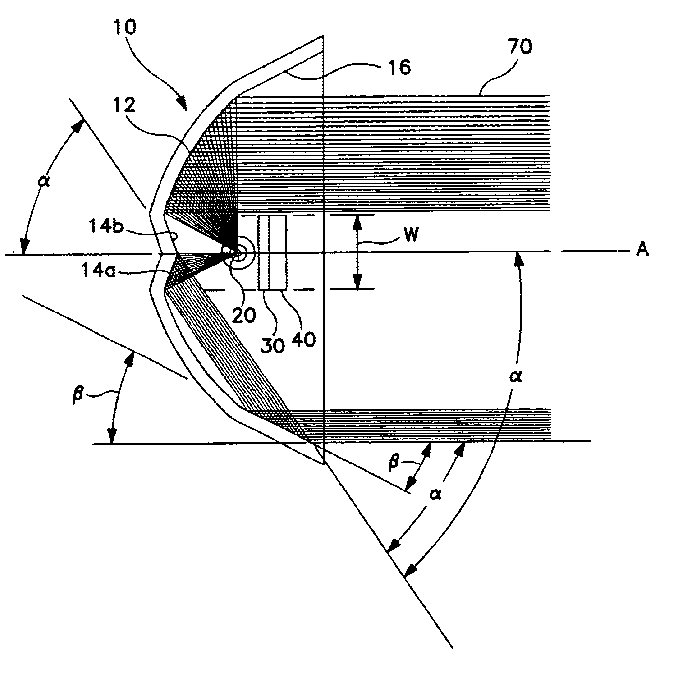
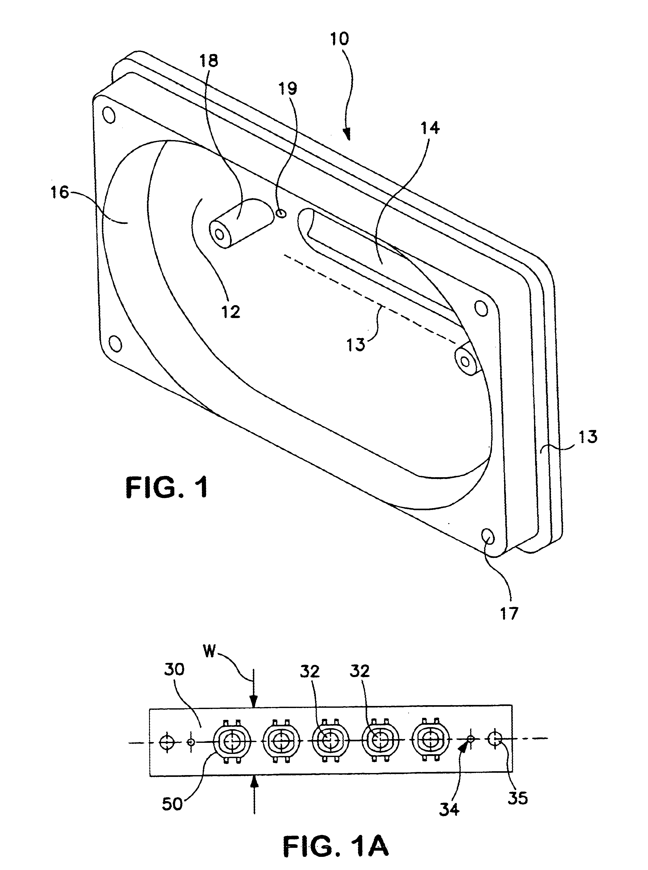
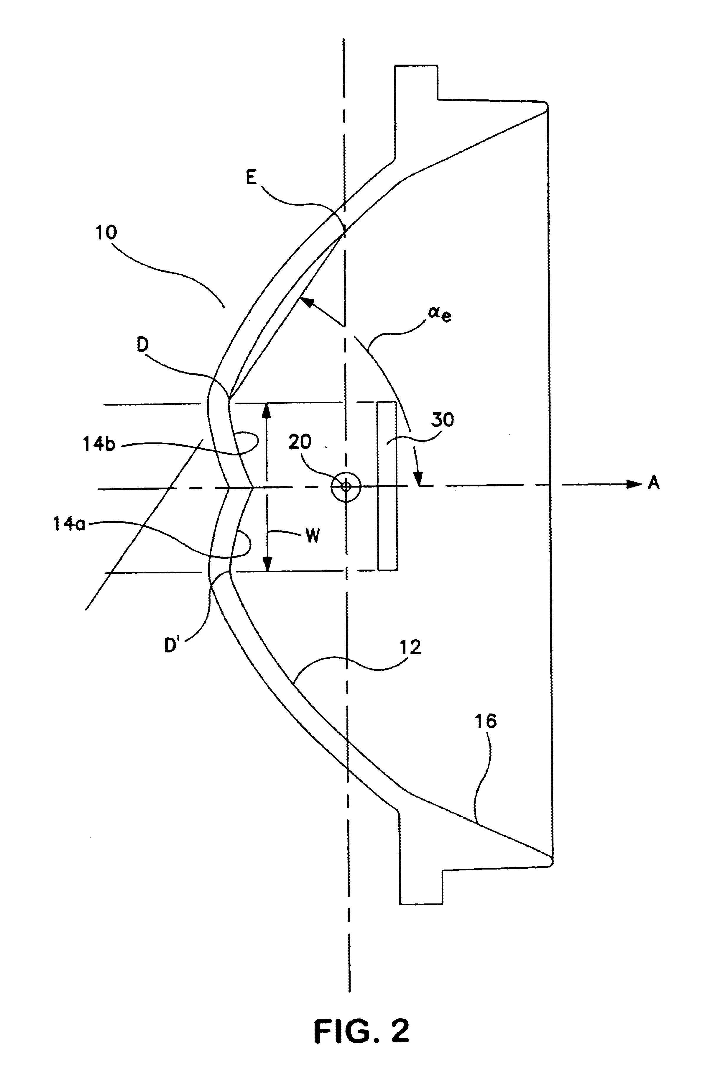
Referring more particularly to FIGS. 1-6 wherein like numbers refer to similar parts, exemplary reflectors are designated by the numeral 10. FIG. 1 is a perspective view of an exemplary reflector 10 having a generally rectangular perimeter, a flange 13 surrounding the perimeter and fastener receptacles 17 in each corner. The overall shape, location of the flange 13 and fastener receptacles 17 allow the reflector 10 to fit into the structural envelope for a preexisting light unit which employed a non-LED light source.

The reflector 10 includes mounting legs 18 inside the reflector to which a PC board 30 such as that illustrated in FIG. 1A is mountable by fasteners (not shown) installed through apertures 35. Conductors (not shown) pass through holes 19 at the rear of the reflector 10 and feed power to the PC board 30 at points 34. Support for the several LEDs 50 is primarily provided by the PC board, to which the LEDs 50 are mounted in a linear array with their respective optical axes ...


PUM


Abstract

A light assembly is configured to produce a large area of light emission from an LED light source. The LED light source is mounted within a concave reflector and oriented to face the rear of the reflector. A compound reflecting surface diverts axial light from the LED away from the axis of the reflector to avoid blockage by the LED support structure. A peripheral reflecting surface redirects the diverted light. The LED light source may be a linear array of LEDs aligned with a linear focal axis of the reflector.

Description

BACKGROUND OF THE INVENTION1. Field of the InventionThe present invention relates generally to warning light devices, and more particularly to shallow depth, large area light assemblies and to warning light assemblies incorporating an LED light source.2. Description of the Related ArtThe prior art contains numerous examples of alternative light sources, reflectors and lenses arranged to produce particular intensities and distributions of light suited for a particular purpose. Of primary concern to designers of lights are the related concepts of efficiency and illumination distribution. By efficiency, it is meant that lighting designers are concerned with both producing the maximum quantity of light (lumens) per unit of energy (watts of electricity) and transforming that light into a useful pattern with minimal losses. Distribution refers to the precision with which a light fixture arranges the light into a desired pattern. The concept of efficiency is related to the concept of distr...

Claims


Application Information

Patent Timeline
IPC IPC(8): F21V29/00F21V7/09F21V7/00F21V19/00
CPCF21S48/328F21V7/0008F21V7/005F21V7/09F21V29/76F21V29/004F21V19/0055F21Y2101/02F21Y2103/003Y10S362/80F21Y2103/10F21Y2115/10F21V29/70F21S45/47
Inventor SMITH, TODD J.LYONS, JON H.
Owner WHELEN ENGINEERING COMPANY
Features
  • Generate Ideas
  • Intellectual Property
  • Life Sciences
  • Materials
  • Tech Scout
  • Unparalleled Data Quality
  • Higher Quality Content
  • 60% Fewer Hallucinations
Learn More