Anti-static, anti-reflection coating

Inactive Publication Date: 2005-02-08
CARL ZEISS VISION AUSTRALIA HO
View PDF42 Cites 90 Cited by
  • Summary
  • Abstract
  • Description
  • Claims
  • Application Information

AI Technical Summary

Benefits of technology

[0030]Preferably, the process of evaporation is assisted by providing the substrate surface with extra energy from a source such as an ion beam. With ion-assisted deposition, low-energy ion bombardmen

Problems solved by technology

However, in practice it has proven to be virtually impossible to produce an anti-reflection coating for an ophthalmic lens product where the coating is highly transparent and truly is substantially static

Method used


Image

  • Anti-static, anti-reflection coating
  • Anti-static, anti-reflection coating
  • Anti-static, anti-reflection coating

Examples


first preferred embodiment

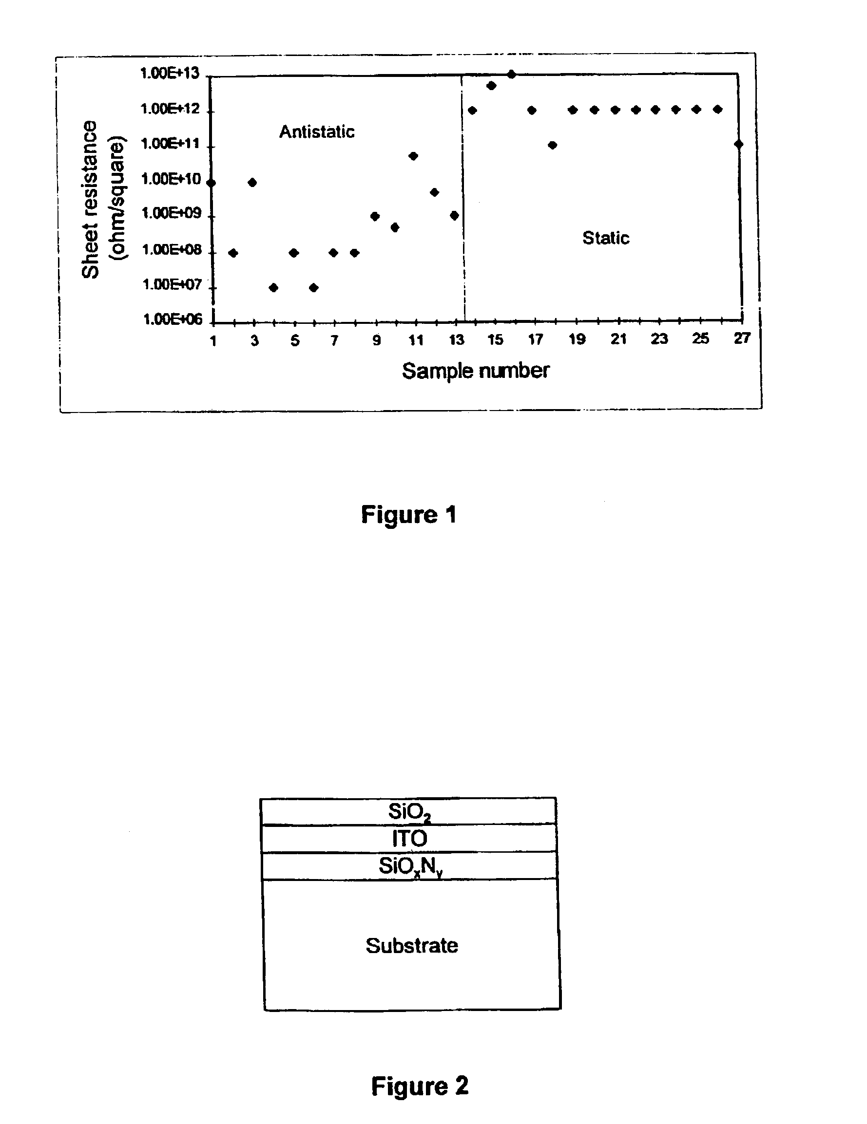
[0061]In accordance with a first preferred embodiment of the present invention, an anti-reflection coating (in the form of a thin film) comprising an electrically conductive layer of indium-tin oxide (ITO) was deposited on a number of transparent substrates by reactive sputtering in order to test for deposition rate, absorption, optical properties, static properties and resistivity properties.

[0062]The transparent substrates were polycarbonate and glass sheets for the determination of deposition rate and absorption, CR-39 flat substrates for resistivity measurements, and hard coated CR-39 plano lenses for both optical and static properties.

[0063]In relation to the various parameters measured, film thicknesses and refractive indices were estimated by fitting calculated spectra to the average of three reflection measurements obtained on a spectrophotometer; film absorption was calculated from reflection and transmission spectra; luminous (photopic) absorption was chosen as a represent...


PUM

PropertyMeasurementUnit
Thicknessaaaaaaaaaa
Thicknessaaaaaaaaaa
Thicknessaaaaaaaaaa

Abstract

An anti-static, anti-reflection, transparent coating for a transpatent substrate, the coating including at least one electrically conductive layer, wherein the sheet resistance of the coating is less than about 1010 ohm/square. The coating is preferably higher transparent.

Description

[0002]This is a continuation of Ser. No. 09 / 491,407, filed Jan. 26, 2000, now abandoned.FIELD OF THE INVENTION[0003]The present invention relates to anti-reflection coatings for transparent substrates, such as ophthalmic lenses, the coating being such as to provide anti-static properties.BACKGROUND OF THE INVENTION[0004]Ophthalmic lenses have traditionally been formed as a single integral body of glass or plastic. However, lenses are now also fabricated by laminating two lens wafers together with transparent adhesive. Regardless of how they are constructed, ophthalmic lenses often include an anti-reflection coating to improve transmittance of visible light.[0005]Attempts have been made to provide anti-static, anti-reflection coatings (for a variety of products), and these attempts have largely centred on the theory of producing an electrically conductive (and thus substantially static resistant) anti-reflection coating. However, in practice it has proven to be virtually impossible t...

Claims


Application Information

Patent Timeline
IPC IPC(8): G02B1/11G02B1/10
CPCG02B1/116G02B2207/121Y10T428/269Y10T428/265Y10T428/24975C03C17/3417C03C17/3435C03C2217/734C03C2217/948G02B1/16
Inventor MARECHAL, NADINE GENEVIEVEBLACKER, RICHARD SIMON
Owner CARL ZEISS VISION AUSTRALIA HO
Why Eureka
Try Eureka