Computer drive mounting device and method

a computer drive and mounting device technology, applied in computing, electrical equipment casings/cabinets/drawers, instruments, etc., can solve the problems of affecting direct impact on the profitability of the enterprise, and quality control rejection at the factory, so as to improve the mounting arrangement of the computer drive and improve the mounting method

Inactive Publication Date: 2005-02-08
AXXION GROUP CORP
View PDF9 Cites 15 Cited by
  • Summary
  • Abstract
  • Description
  • Claims
  • Application Information

AI Technical Summary

Benefits of technology

The present invention provides an improved computer drive mounting arrangement and an improved method of mounting a computer drive.
One embodiment of the present invention is a mounting device for a computer drive that includes a flexible locking plate and one or more tabs for securing the drive. A contact point allows a portion of the locking plate to be elastically deflected or flexed out of a plane that substantially corresponds to the plane of the flexible locking plate when not flexed.
Another form of the present invention is a computer drive mounted within a computer drive cage that includes a drive mounting assembly that is made up of a flexible locking plate that includes one or more tabs for securing the drive. A contact point that allows a portion of the locking plate to be reversibly flexed out of a plane that generally corresponds to the plane of the flexible locking plate when it is not flexed, and the one or more tabs connect to the computer drive and hold it substantially within the drive cage.
Yet another form of the present invention is a method of mounting a computer drive that includes the steps of reversibly flexing a flexible locking plate that is attached to a drive cage, such that the plane of the locking plate in the flexed position is not substantially planar with the portion of the drive cage to which the flexible locking plate is attached, and placing a computer drive at least partially within the drive cage, and releasing the reversibly flexed flexible locking plate such that the flexed portion returns to a position that is substantially planar to the portion of the drive cage to which the flexible locking plate is attached. This results in the contacting one or more mounting tabs of the flexible locking plate with the computer drive.

Problems solved by technology

Each added step in the manufacturing process adds to the expense of the finished product.
Any change that allows the assembler to increase the number of units produced in a given period will directly impact the profitability of the enterprise.
The difficulty of attaching the screws also leads to the potential for assembly defects that may result in a quality control rejection at the factory, or worse, a defect in the possession of the end user requiring a return and remanufacture.
Even when properly installed, the use of screws is still problematic.
The small size and metallic nature of the screws gives rise to additional problems.
Since the screws are used in confined spaces, they are difficult to handle and can be dropped into positions that may lead to short circuiting or other damage to expensive components.
If the consumer does not have the appropriate tools, or expertise to use them, there is the possibility that they will damage either the component that they are working on, or another component near by.
This is especially true with computer drives mounted by small hard to reach screws in chassis positions cluttered by the presence of other system components.

Method used


Image

  • Computer drive mounting device and method
  • Computer drive mounting device and method
  • Computer drive mounting device and method

Examples


Embodiment Construction

Although making and using various embodiments of the present invention are discussed in detail below, it will be appreciated that the present invention provides many applicable inventive concepts that may be embodied in a wide variety of contexts. The specific embodiments discussed here are meant to be illustrative of specific examples of how the present invention may be made and used and are not meant to limit the scope of the invention in any way.

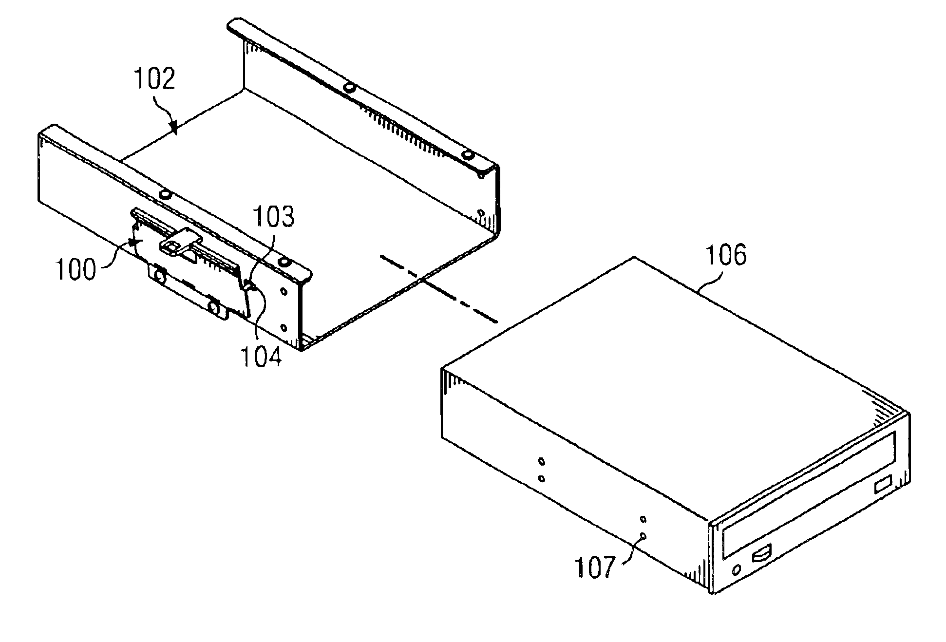
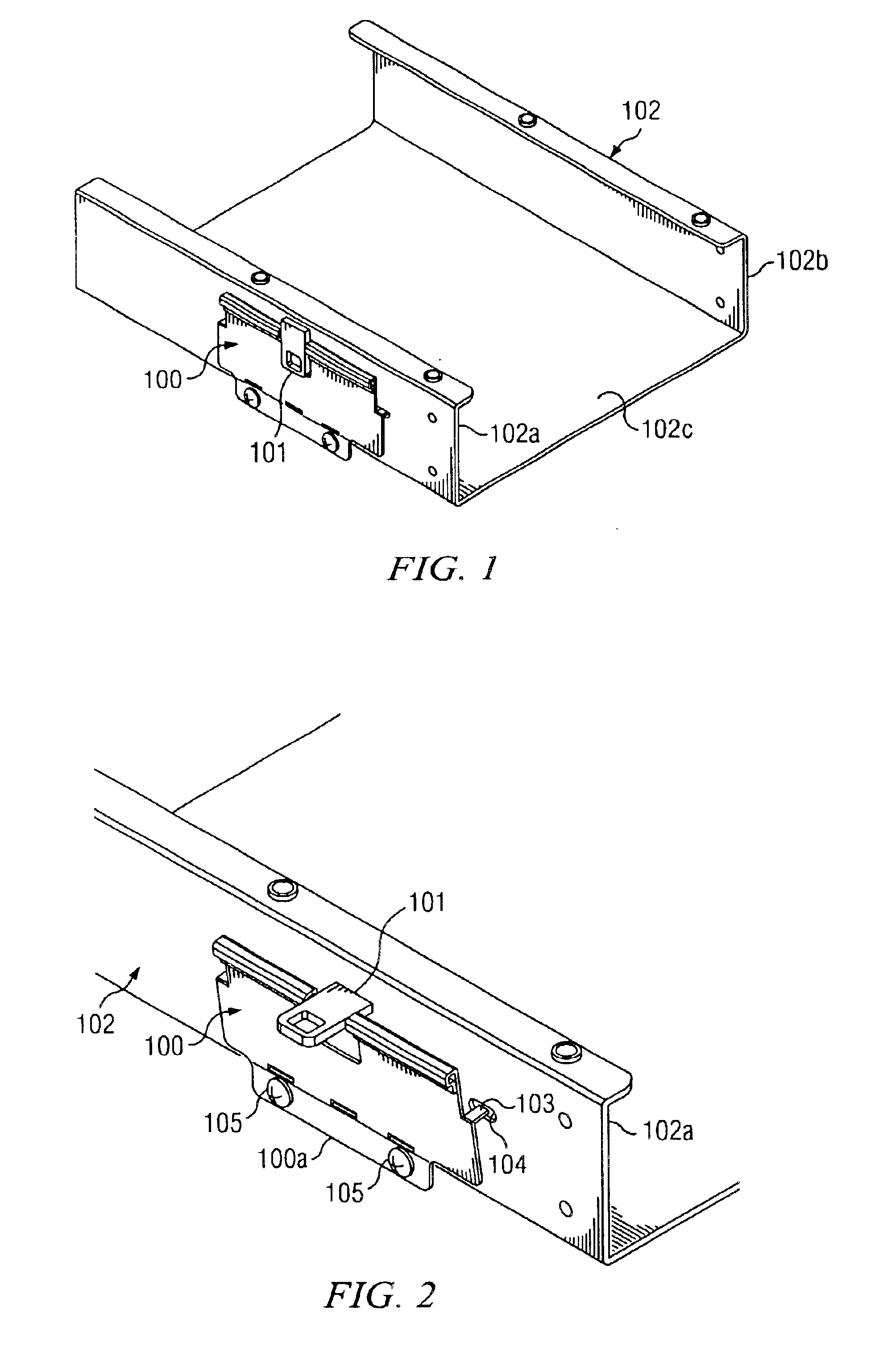
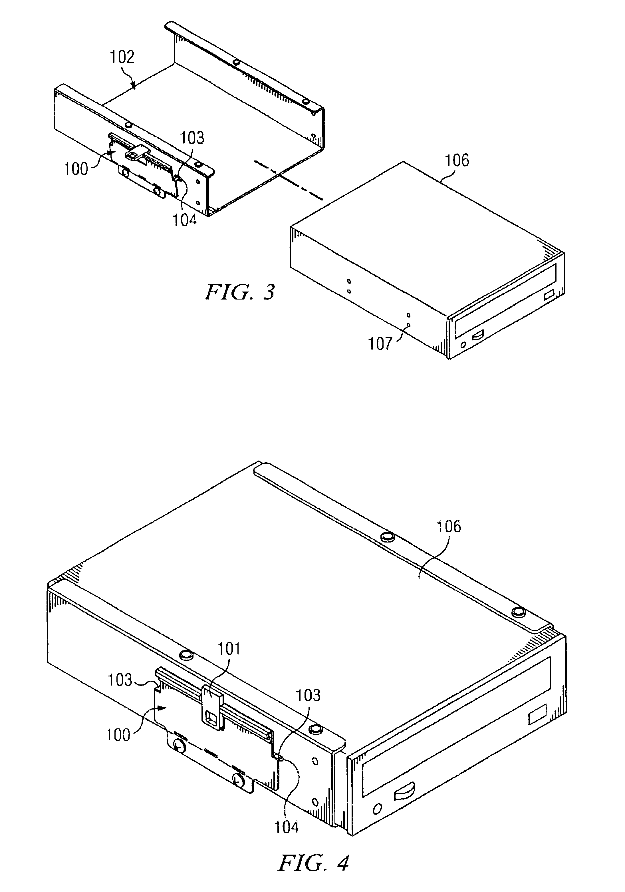
Referring to FIG. 1, the drive attachment device of the invention is characterized by a flexible locking plate 100 that includes a rotateable lever 101 is attached to a drive cage 102. Cage 102 is shown as a generally channel shaped member having opposed generally planar side walls 102a and 102b interconnected by an integral wall 102c. The flexible locking plate 100 is depicted in the closed or mounted position in FIG. 1. In this position a first plate portion 100a of the locking plate 100 is substantially contiguous with the sidewall 102...


PUM


Abstract

The present invention includes a mounting device for a computer drive that includes a flexible locking plate and one or more tabs for securing the drive. A contact point allows a portion of the locking plate to be reversibly flexed out of a plane that substantially corresponds to the plane of the flexible locking plate when not flexed is used to effect.

Description

FIELD OF INVENTIONThe present invention relates to computers and computer manufacturing and more particularly to an apparatus and method to easily mount a computer drive within a drive cage.BACKGROUND OF THE INVENTIONThe consumer market in computers is very competitive and those manufacturers that are successful rely on their ability to rapidly assemble their products to meet both customer expectations and the need for high throughput in order to maintain profitability. Because of the highly competitive market in which these manufacturers operate, they seek to maximize their returns through the efficient use of their labor resources. Each added step in the manufacturing process adds to the expense of the finished product. Any change that allows the assembler to increase the number of units produced in a given period will directly impact the profitability of the enterprise.A computer drive, such as for example a hard drive or a floppy disc drive is generally attached to a drive cage ...

Claims


Application Information

Patent Timeline
Patent Type & Authority Patents(United States)
IPC IPC(8): G06F1/18
CPCG06F1/187G06F1/184
Inventor WILLIAMS, DAVID D.MORIEL, JORGE A.GIBSON, RICHARD A.MERCADO, FRANCISCO M.
Owner AXXION GROUP CORP
Why Eureka
Try Eureka