Optical object recognition system

a technology of optical object recognition and optical object, which is applied in the field of optical object recognition system, can solve the problems of large amount of time required for determining whether or not distances are within a specified range, large error generation of distance values for respective windows as the distance becomes larger

Inactive Publication Date: 2005-02-08
HONDA MOTOR CO LTD
View PDF7 Cites 111 Cited by
  • Summary
  • Abstract
  • Description
  • Claims
  • Application Information

AI Technical Summary

Benefits of technology

The controller may comprise a micro-controller which typically includes a central processing unit (CPU) or a micro-processor, a read-only memory (ROM) containing control programs that when executed by the processor pe

Problems solved by technology

However, when clustering (that corresponds to the abovementioned block formation) is performed with larger number of windows (that corresponds to the abovementioned calculation areas) so that measured distance values can be obtained with a greater degree of fineness, an extremely large amount of time is required for determining wheth

Method used


Image

  • Optical object recognition system
  • Optical object recognition system
  • Optical object recognition system

Examples


Embodiment Construction

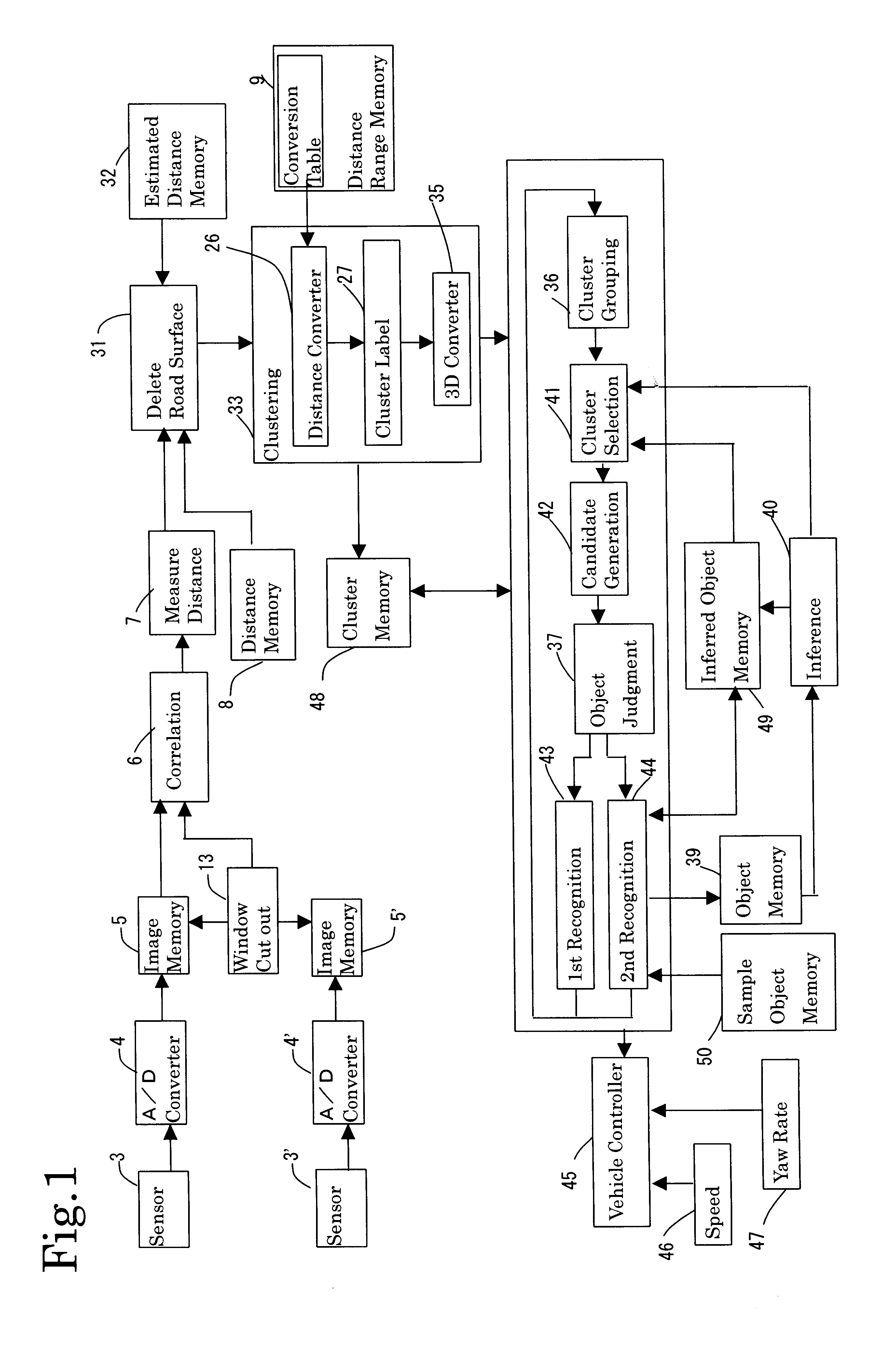
The invention will now be described relative to preferred embodiments referring to attached figures. FIG. 1 is an overall block diagram of an object recognition system in accordance with one embodiment of the present invention. Other than the sensors 3 and 3′, all the blocks in FIG. 1 may be incorporated in a controller which comprises a single chip or multiple chip semiconductor integrated circuit. Thus, FIG. 1 shows functional blocks of the controller. Respective functions of the blocks are performed by executing respective programs stored in the ROM of the controller.

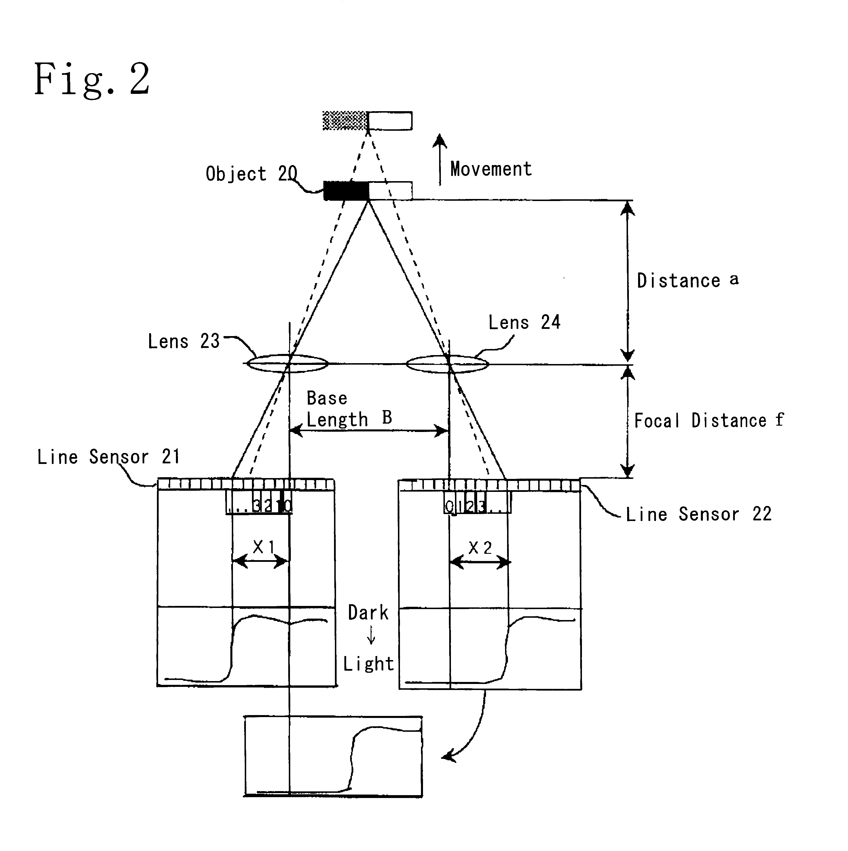
FIG. 2 is a diagram which indicates the distance measurement principle based on the triangulation method used in the present embodiment. First, a distance measurement method using a pair of image sensors will be described with reference to FIG. 2. A line sensor 21 and lens 23 constituting one of the abovementioned pair of image sensors are installed at a specified distance, i. e., at a distance equal to the base line...


PUM


Abstract

An object recognition system comprises a memory for storing a plurality of distance ranges with different distance labels associated with respective distance ranges. The controller converts measured distance values into distance labels according to distance ranges to which the distance values belong. The controller groups the sections or windows of a captured image based on assigned distance labels. Detection area or viewing area of the sensors is divided into a plurality of distance ranges according to tolerance of the measured distance such that broader distance range is defined as the distance from the system is larger. The controller scans the windows with distance labels using a template that defines a joining relationship for the windows and assigns each window with a cluster label that is a combination of the distance label and a occurrence indicia, which is the same for the windows that satisfy the joining relationship. The controller unites the windows having the same cluster labels into a cluster, generates three dimensional data of each of said clusters and combines the clusters that are positioned close to each other based on the three dimensional data to form a candidate of a physical object. The system includes a memory for storing three dimensional data of one or more physical objects that were recognized in previous recognition cycle. The controller infers a physical object which would be recognized in the current cycle based on the stored data and a speed of the vehicle relative to the physical object. The controller compares the inferred physical object with said candidate of a physical object to recognize a physical object.

Description

FIELD OF THE INVENTIONThe present invention relates to an optical object recognition system which detects objects in front of a vehicle such as an automobile, etc., using image capturing apparatus having cameras mounted on this vehicle. More specifically, the present invention concerns an object recognition system, which recognizes the characteristic features of objects using a plurality of windows in the captured images.BACKGROUND OF THE INVENTIONIn recent years, devices which determine the distance and size of objects in front of a vehicle, and which appropriately control the vehicle in accordance with this judgment, have been proposed for the purpose of improving the safety of vehicle operation.Japanese Patent Application Kokai No. Hei 9-79821 describes one example of a device in which an optical distance measuring device consisting of two light-receiving elements is used to determine whether an object whose distance has been detected is a physical object or a road area (includin...

Claims


Application Information

Patent Timeline
IPC IPC(8): G01C3/08G01S5/16G01S5/00G06K9/32G06K9/62G01C3/06G06V10/762
CPCG01C3/085G01S5/16G06K9/00201G06K9/00818G06K9/00805G06K9/342G06K9/6218G06K9/3241G06K2209/23G06V20/64G06V20/582G06V20/58G06V10/255G06V10/267G06V2201/08G06V10/762G06F18/23
Inventor NISHIGAKI, MORIMICHISAKA, MASAKAZU
Owner HONDA MOTOR CO LTD
Why Eureka
Try Eureka