Assemblies adapted to be affixed to containers containing fluid and methods of affixing such assemblies to containers

a technology for affixed assemblies and containers, applied in the field of assemblies, can solve the problems of rough surface, metallic nuts and bolts, adversely affecting the fluid inside the tank,

Inactive Publication Date: 2005-02-15
SMAR RES CORP
View PDF9 Cites 44 Cited by
  • Summary
  • Abstract
  • Description
  • Claims
  • Application Information

AI Technical Summary

Benefits of technology

les through the container. Another advantage of the present invention is that elements of the assembly which are positioned inside the container preferably do not have sharp edges or roughened surfaces, such that residue may not collect on those elements of the assembly which are positioned inside the container. For example, the elements of the assembly which are positioned inside the container can be manufactured from a flexible material, such as rubber. Consequently, the fluid inside the container would not be adversely affected by the elements of the assembly which are positioned inside the container.
These and other advantages can be realized with an exemplary embodiment of the present invention, in which an assembly adapted to be affixed to a container (e.g., a tank) containing fluid, and a method for affixing the assembly to the container are provided such that contact pressure is applied to a surface of the container (e.g., using a first arrangement). In this manner, a second arrangement is affixed to the container without piercing the surface of the container. Specifically, the first arrangement may be positioned in the vicinity of an opening or a fore in the container, and the second arrangement (e.g., a sensor arrangement) may include a portion situated within the opening. Moreover, the first arrangement can be adapted to affix the second arrangement to the container without piercing a surface of the container by applying the contact pressure to the surface (e.g., an exterior surface) of the container.
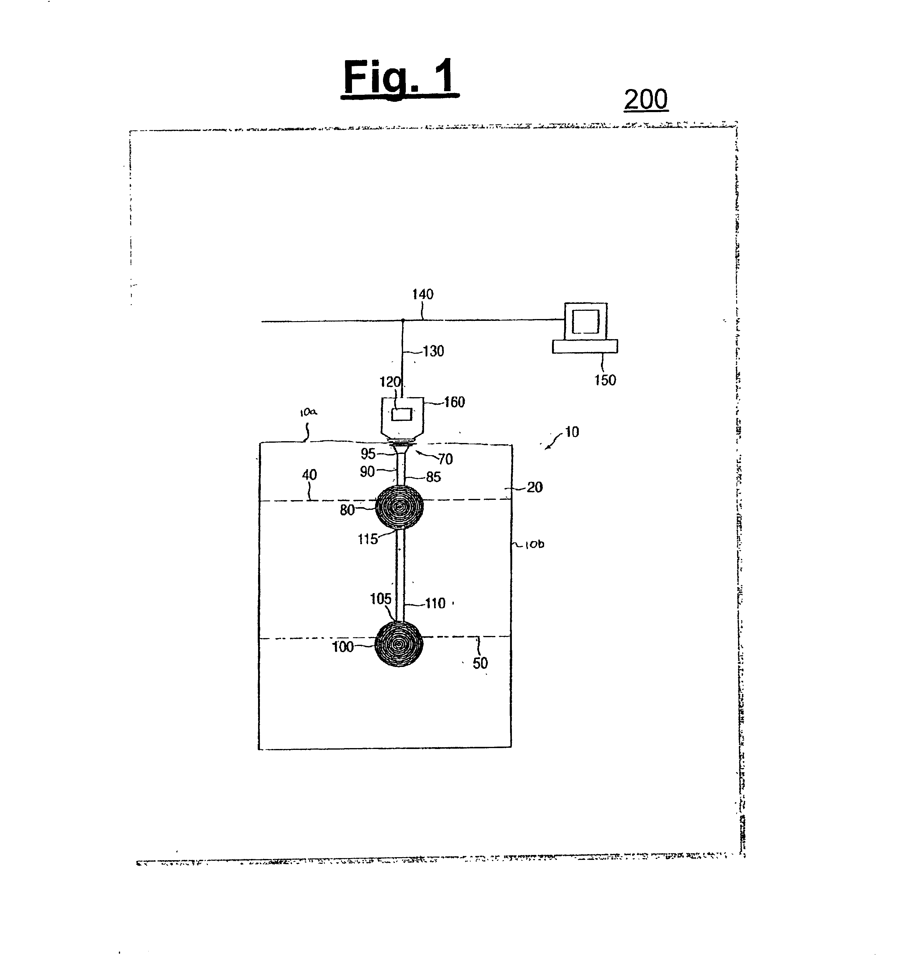
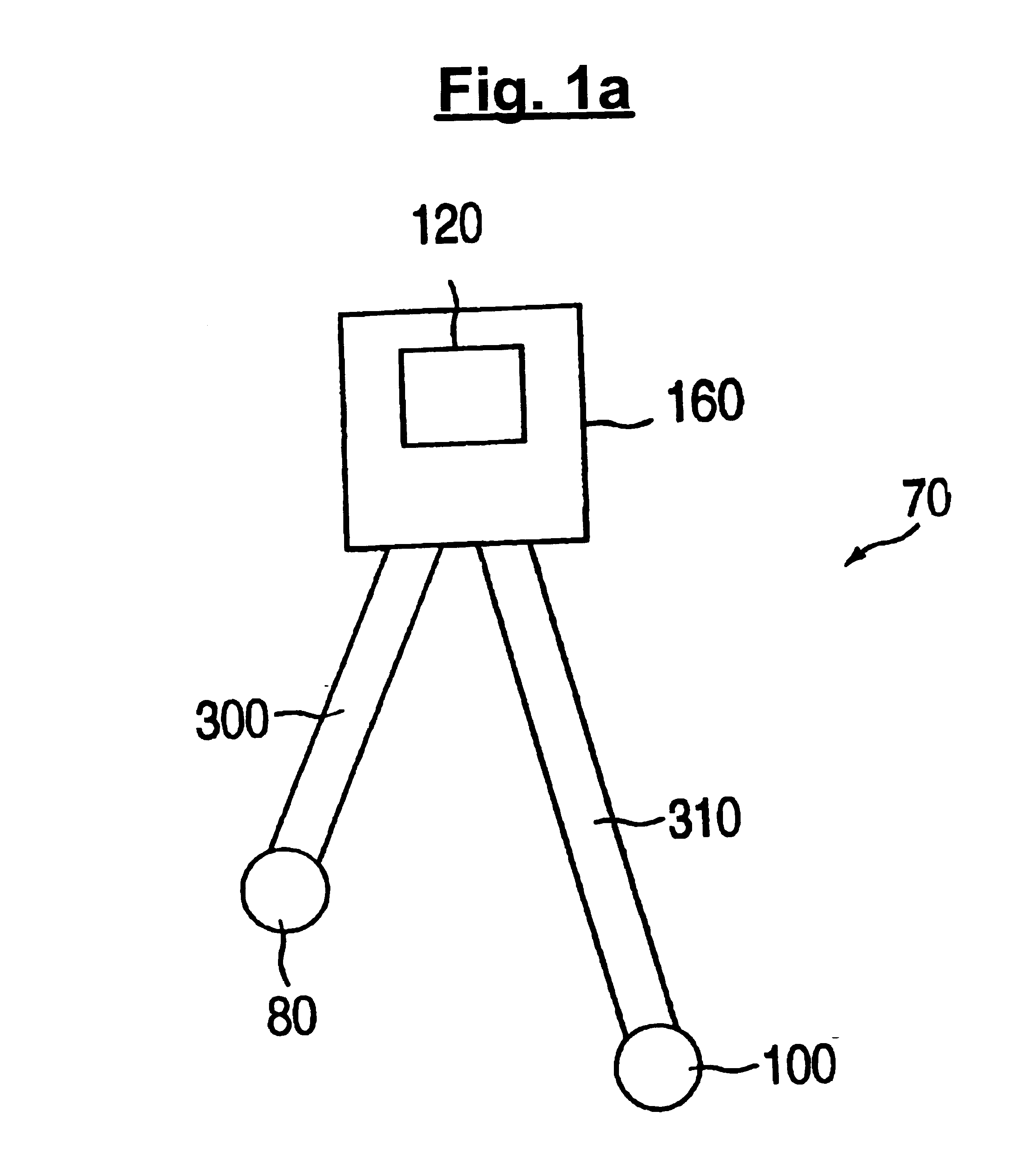
In another exemplary embodiment of the present invention, the second arrangement can include a housing arrangement, and a portion of the housing arrangement may be positioned inside the container, or the housing arrangement can be entirely situated outside the container. The housing arrangement can contain a first sensor fluid and a second sensor fluid, such that the housing arrangement prevents the first sensor fluid and the second sensor fluid from mixing with the sample fluid. The second arrangement also can include a first sensor positioned within the container or situated outside the container at a first fluid level. The first sensor can be connected to the housing arrangement, and may be adapted to detect a fluid pressure at the first fluid level by acting on the first sensor fluid. Similarly, the second arrangement can include a second sensor positioned within the container or situated outside the container at a second fluid level which is below the first fluid level. The second sensor can be connected to the housing arrangement, and may be adapted to detect a fluid pressure at the second fluid level by acting on the second sensor fluid. The second arrangement may further include a transmitter positioned outside the container.
The transmitter can be coupled to the housing arrangement, or may be positioned inside the housing arrangement, and the transmitter is adapted to communicate with the first sensor via the first sensor fluid and with the second sensor via the second sensor fluid. The transmitter also may be adapted to generate a signal corresponding to a density of the fluid. Moreover, the second arrangement may include a calculating device coupled to the transmitter, which is adapted to calculate the density of the fluid based on the signal.
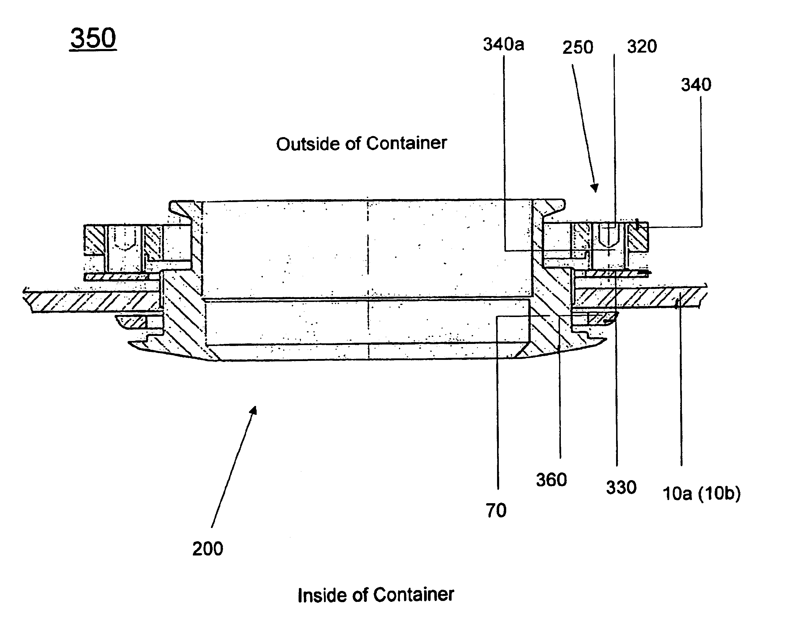
In still another exemplary embodiment of the present invention, the first arrangement can include one or more securing elements (e.g., a threaded element, such as a bolt or a screw) positioned outside of the container. Each securing element may be directly or indirectly connected to the housing arrangement, and can also be adapted to apply the contact pressure to the surface of the container without piercing the surface of the container. For example, each securing element can apply the contact pressure to the exterior surface of the container when rotated in a predetermined direction. The first arrangement also can include a contact member (e.g., a washer) positioned between a corresponding securing element and the container. As such, each securing element may apply the contact pressure to the surface of the container via the corresponding contact member. The first arrangement can further include a plate having a hole or a plurality of holes formed therethrough. The plate can be connected to the housing arrangement, and each hole may be adapted to receive a securing element.
In yet another exemplary embodiment of the present invention, each of the sealing elements may be directly or indirectly connected to the housing arrangement, and can be mechanically coupled to the first arrangement. Moreover, when a particular securing element applies the contact pressure to a first surface of the container, such sealing element moves in a direction towards a second surface of the container. For example, when the securing element applies the contact pressure to the exterior surface of the container, the sealing element moves in a direction towards the interior surface of the container. Moreover, when the sealing elements contact the interior surface of the container, a seal is formed. Consequently, the fluid cannot escape from the container.

Problems solved by technology

Moreover, such nuts and bolts are metallic, and have roughened surfaces.
When the tank is used over a period of time, the roughened surfaces of the nuts and bolts may collect residue, and such residue may adversely affect the sample fluid inside the tank.

Method used


Image

  • Assemblies adapted to be affixed to containers containing fluid and methods of affixing such assemblies to containers
  • Assemblies adapted to be affixed to containers containing fluid and methods of affixing such assemblies to containers
  • Assemblies adapted to be affixed to containers containing fluid and methods of affixing such assemblies to containers

Examples


Embodiment Construction

Exemplary embodiments of the present invention and their advantages may be understood by referring to FIGS. 1-5, like numerals being used for like corresponding parts in the various drawings.

Referring to FIG. 1, an exemplary embodiment of a particular arrangement 200 (e.g., a sensor arrangement) for determining a characteristic of a sample fluid 20 (e.g., beer) within a container (e.g., a tank, such as a beer tank) is provided. For example, the particular arrangement 200 of the present invention may be similar to the arrangement described in U.S. Pat. No. 6,234,019. Specifically, the particular arrangement 200 may include a housing arrangement 70, a first sensor 80, a first extension 90, a second sensor 100, a second extension 110, a transmitter 120, a first data bus 130, a second data bus 140 and a computer system 150.

The housing arrangement 70 can include the first extension 90 and / or the second extension 110. The first sensor 80, the second sensor 100 and / or the transmitter 120 c...


PUM

PropertyMeasurementUnit
contact pressureaaaaaaaaaa
pressureaaaaaaaaaa
densityaaaaaaaaaa

Abstract

An assembly adapted to be affixed to a container which contains a sample fluid, and a method of affixing the assembly to the container, are provided. In particular, a contact pressure can be applied to a surface of the container, such that a particular arrangement, which has a portion situated within an opening of the container, is affixed to the container without piercing the surface of the container. For example, the container can be a tank, the particular arrangement can be a sensor arrangement, and a further arrangement can be used to affix the particular arrangement to the container. Moreover, the contact pressure preferably can be applied to an exterior surface of the container so that the further arrangement may be more accessible to a user of the assembly.

Description

FIELD OF THE INVENTIONThe present invention relates generally to an assembly adapted to be affixed to a container which contain fluid, and a method for affixing such assembly to the container. In particular, the present invention is directed to an assembly in which a contact pressure is applied to a surface of the container, such that a particular arrangement is affixed to the container without piercing the surface of the container and to a method for affixing this assembly to the container.BACKGROUND OF THE INVENTIONConventional arrangements (e.g., conventional sensor arrangements) may be used to determine a characteristic of fluid within a container (e.g., a tank). For example, the conventional arrangements can be used to determine a temperature of the fluid, a pressure associated with the fluid, a density of the fluid, etc. An exemplary conventional arrangement as described in U.S. Pat. No. 6,234,019, the entire disclosure of which is incorporated herein by reference, may be affi...

Claims


Application Information

Patent Timeline
Patent Type & Authority Patents(United States)
IPC IPC(8): G01N9/00G01N9/26
CPCG01N9/26
Inventor ALVES, EVARISTO ORELLANAJUNIOR, CLOVIS CATANANTI
Owner SMAR RES CORP
Why Eureka
Try Eureka