
Engine with variable valve mechanism

a valve mechanism and variable technology, applied in valve drives, machines/engines, mechanical equipment, etc., can solve problems such as requiring a redesigned cylinder head architectur

Active Publication Date: 2005-02-15
MECHADYNE INT
View PDF3 Cites 21 Cited by
  • Summary
  • Abstract
  • Description
  • Claims
  • Application Information

AI Technical Summary

Benefits of technology

The present invention seeks to provide an alternative installation package better suited to engines with a rocker operated valve train which avoids the need to remodel the cylinder head while still permitting the event duration to be modified.
It is preferred for the valve mechanism to be symmetrical so as to avoid any twisting moment on the pivot shaft of the first rocker about an axis transverse to the axis of rotation of the cams.

Problems solved by technology

A disadvantage of this earlier proposal is that it requires the cylinder head architecture to be redesigned.

Method used


Image

  • Engine with variable valve mechanism
  • Engine with variable valve mechanism
  • Engine with variable valve mechanism

Examples


Embodiment Construction

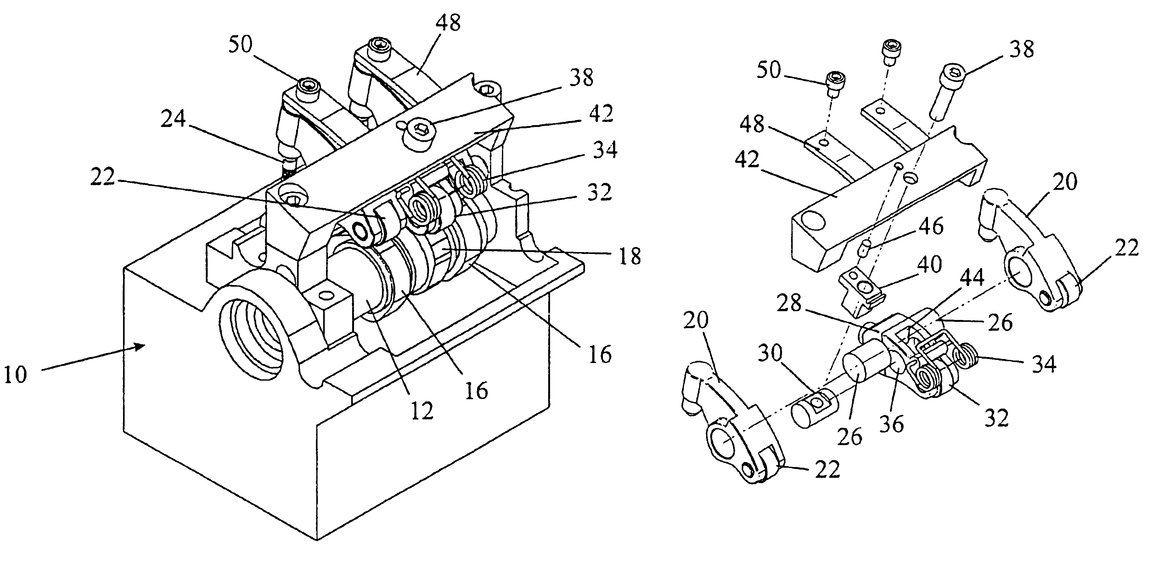
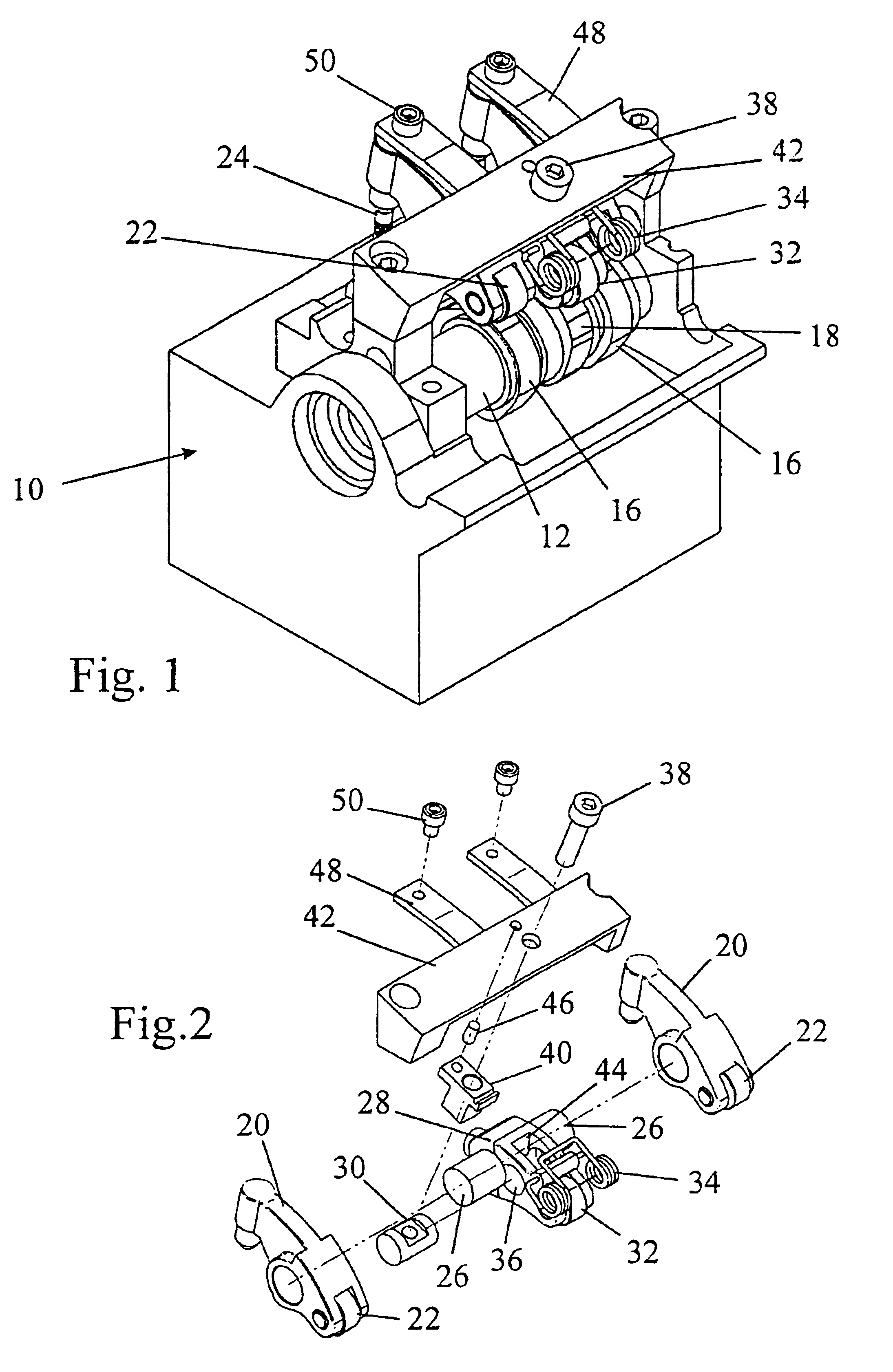
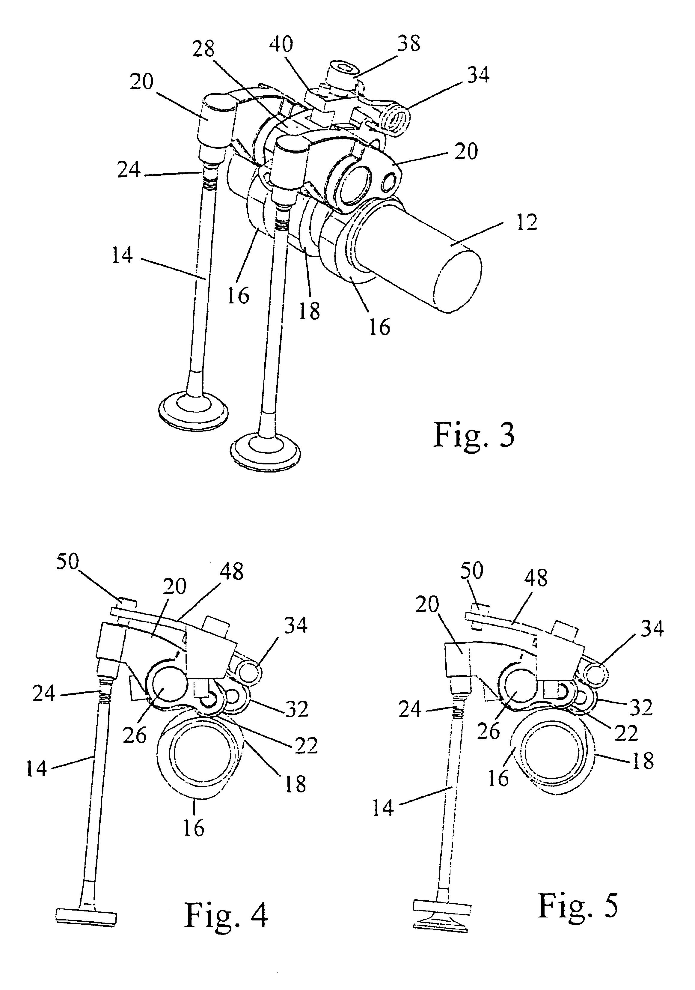
The engine shown in part in FIG. 1 has a cylinder head generally designated 10. A camshaft 12 is journalled in the cylinder head 10 and has two sets of cams that are mounted for a limited degree of angular movement relative to one another. For example, the camshaft may comprise a central shaft secured for rotation with one set of cams and surrounded by a sleeve that is rotatable with a second set of cams.

A phase change mechanism such as shown in FIG. 10 of the above referenced PCT / GB2002 / 003804 is used to vary the phase of the sets of cams relative to one another. Another such phase change mechanism may be used to adjust the phases of both sets of cams simultaneously in relation to the phase of the engine crankshaft. The construction and operation of the phase change mechanism will not be described herein in detail as it is in itself well known. Furthermore, numerous alternative constructions of phase change mechanism, as disclosed in the prior art, may be used to vary the phases of...


PUM


Abstract

An overhead camshaft internal combustion engine is disclosed having a valve mechanism which comprises an intake or exhaust poppet valve 14 having a valve stem operated by two cams 16 and 18 mounted for rotation about a common axis. A first rocker 20 mounted on a pivot shaft 26 acts between the first cam 16 and the valve 14. A second rocker 28 is mounted in the engine on a fixed pivot shaft 30 and acts between the second cam 18 and the pivot shaft 26 of the first rocker 20, to raise and lower the pivot point 26 of the first rocker 20 cyclically in synchronism with the rotation of the second cam 18.

Description

FIELD OF THE INVENTIONThe present invention relates to an overhead camshaft internal combustion engine having a valve mechanism which enables the valve event duration to be varied.BACKGROUND OF THE INVENTIONThe closest prior art to the present invention is believed to be WO03 / 016684 which is incorporated herein by reference. In the latter patent specification, a summation lever following the movements of two cams is pivotably mounted on a rocker to open a poppet valve by an amount equal to the sum of the lifts occasioned by the separate cams. By varying the phase of the two cams relative to one another, the event duration and the valve lift can be modified and by simultaneously varying the phase of both cams in relation to the engine crankshaft, the valve timing can be modified.A disadvantage of this earlier proposal is that it requires the cylinder head architecture to be redesigned.OBJECT OF THE INVENTIONThe present invention seeks to provide an alternative installation package be...

Claims


Application Information

Patent Timeline
IPC IPC(8): F01L1/08F01L13/00
CPCF01L1/08F01L1/267F01L13/0047Y10T74/2107F01L2105/00F01L2305/00
Inventor METHLEY, IAN
Owner MECHADYNE INT
Learn More