Food waste disposer having a variable speed motor

a technology of food waste and motor, which is applied in the direction of gas current separation, grain treatment, agriculture, etc., can solve the problems of increased noise and vibration, affecting the grind performance of the disposer, and unpleasant odors

Inactive Publication Date: 2005-02-15
EMERSON ELECTRIC CO
View PDF54 Cites 59 Cited by
  • Summary
  • Abstract
  • Description
  • Claims
  • Application Information

AI Technical Summary

Benefits of technology

To that end, the present invention provides a food waste disposer having an upper food conveying section, a motor section, a central grinding section and a controller. The upper food conveying section includes a housing forming an inlet to receive food waste. The motor section includes a switched reluctance machine having a rotor and a stator. The rotor imparts rotational movement to a rotatable shaft. The central grinding section is disposed between the food conveying section and the motor section. The food conveying section conveys food waste to the grinding section. The grinding section includes a grinding mechanism where a portion of the grinding mechanism is mounted to the rotatable shaft. The controller is electrically connected to the stator to control the switched reluctance machine. The controller is capable of directing rotational movement to the rotatable shaft and the portion of the grinding mechanism mounted to the rotatable shaft. The controller is further capable of maintaining the rotational movement of the rotatable shaft at more than one rotational speed and direction.

Problems solved by technology

It has been found that the selected rotational speed of the grinding plate may affect the grind performance of the disposer for certain types of foods.
Riding results in increased noise and vibration, as well as, residual food left in the grinding chamber after the disposer is turned off.
Over time, residual food may cause unpleasant odors.
Another area of concern with conventional disposers is noise and power consumption.
Higher rotational speeds may produce more noise and consume more power.
A further problem in designing a food waste disposer is jamming.

Method used


Image

  • Food waste disposer having a variable speed motor
  • Food waste disposer having a variable speed motor
  • Food waste disposer having a variable speed motor

Examples


Embodiment Construction

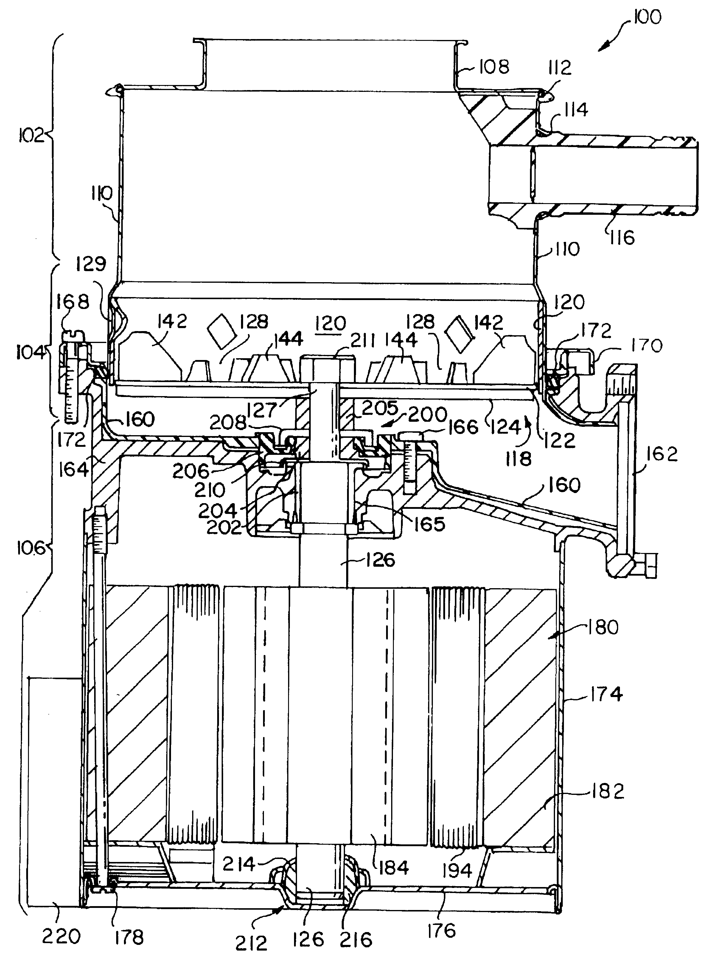
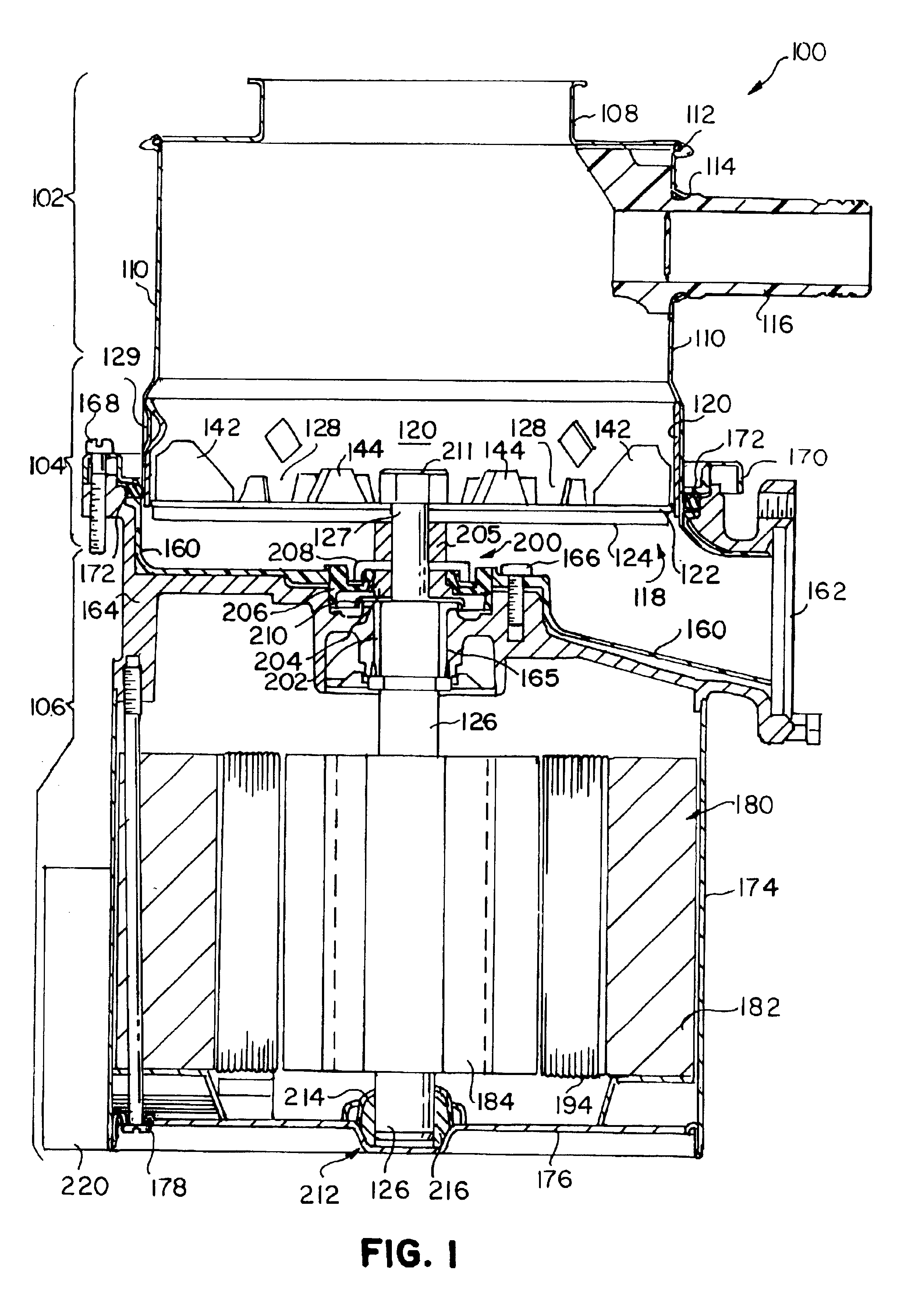
Turning to the drawings, FIG. 1 depicts a food waste disposer 100 embodying the present invention. The disposer 100 may be mounted in a well-known manner in the drain opening of a sink using conventional mounting members of the type disclosed in U.S. Pat. No. 3,025,007, which is owned by the assignee of the present application and incorporated herein by reference in its entirety. The disposer includes an upper food conveying section 102, a central grinding section 104 and a variable speed motor section 106. The central grinding section 104 is disposed between the food conveying section 102 and the variable speed motor section 106.

The food conveying section 102 conveys the food waste to the central grinding section 104. The food conveying section 102 includes an inlet housing 108 and a conveying housing 110. The inlet housing 108 forms an inlet at the upper end of the food waste disposer 100 for receiving food waste and water. The inlet housing 108 is attached to the conveying housin...


PUM


Abstract

The present invention provides a food waste disposer having an upper food conveying section, a motor section, a central grinding section and a controller. The upper food conveying section includes a housing forming an inlet to receive food waste. The motor section includes a switched reluctance machine having a rotor and a stator. The rotor imparts rotational movement to a rotatable shaft. The central grinding section is disposed between the food conveying section and the motor section. The food conveying section conveys food waste to the grinding section. The grinding section includes a grinding mechanism where a portion of the grinding mechanism is mounted to the rotatable shaft. The controller is electrically connected to the stator to control the switched reluctance machine. The controller is capable of directing rotational movement to the rotatable shaft and the portion of the grinding mechanism mounted to the rotatable shaft. The controller is further capable of maintaining the rotational movement of the rotatable shaft at more than one rotational speed. The present invention also includes methods of operating a variable speed motor in different operational modes such as idle mode and anti-jamming mode.

Description

FIELD OF THE INVENTIONThe present invention relates generally to food waste disposers and, more particularly, to a food waste disposer having a variable speed motor such as a switched reluctance machine.BACKGROUND OF THE INVENTIONThe fineness and duration of grinding food waste are important considerations in the design and operation of a disposer. Many conventional food waste disposers use a single speed induction motor that rotates a grinding plate to grind food waste. The rotational speed of the grinding plate for most food waste disposers is between 1700 and 1800 rotations per minute (RPM). A food waste disposer having an induction motor is disclosed in U.S. Pat. No. 6,007,006 (Engel et al.), which is owned by the assignee of the present application and incorporated herein by reference in its entirety.It has been found that the selected rotational speed of the grinding plate may affect the grind performance of the disposer for certain types of foods. For example, harder food par...

Claims


Application Information

Patent Timeline
Patent Type & Authority Patents(United States)
IPC IPC(8): B02C18/06B02C18/24E03C1/26E03C1/266B02C18/00
CPCB02C18/24E03C1/2665B02C2018/164
Inventor STRUTZ, WILLIAM F.BERGER, THOMAS R.
Owner EMERSON ELECTRIC CO
Why Eureka
Try Eureka