Magnetic lifting machine using neodymium magnets

a technology of neodymium magnets and lifting machines, which is applied in the direction of magnetic bodies, wellbore/well accessories, manufacturing tools, etc., can solve the problems of high manufacturing cost, lowering magnetization, and exfoliation of the coated film on the magnet, so as to reduce friction, improve credibility and commercial applicability of the machine, and rotate the rotor smoothly

Inactive Publication Date: 2005-02-15
JUNG HYUNG
View PDF3 Cites 24 Cited by
  • Summary
  • Abstract
  • Description
  • Claims
  • Application Information

AI Technical Summary

Benefits of technology

The object of the present invention is to provide a magnetic lifting machine which uses neodymium magnets having excellent coercive force but prevents an antioxidant film on the surface of the neodymium magnets from being exfoliated.
Another object of the present invention is to provide a magnetic lifting machine whereby change of directional positions of a rotor for switching on and off magnetization can be done smoothly, thus enhancing the credibility and commercial applicability thereof.
Another object of the present invention is to provide a magnetic lifting machine which can be manufactured with lower costs and with smaller volume than conventional magnetic lifting machines.
According to the present invention, since the neodymium magnets inserted in the rotor is in contact with the polarity plates via thin anti-exfoliation plates attached thereon, the coated film of the neodymium magnets can be effectively protected from exfoliation caused by the friction which occurs in the course of rotation.
Lubricants such as grease can be supplied to and stored in the plurality of holes to reduce the friction and to allow the rotor to rotate smoothly. By forming these holes on the anti-exfoliation plate, change of operational directions of the rotor to switch on and off the machine can be smoothly achieved, and thus credibility and commercial applicability of the machine can be improved.

Problems solved by technology

The large size of the ferrite magnetic necessitated a relatively large size of the magnetic lifting body in the magnetic lifting machine, which was disadvantageous to use and in view of high manufacturing costs as well.
However, the neodymium magnet has a fatal disadvantage in that it is easily oxidized when exposed to atmosphere, thereby lowering magnetization.
However, use of the coated neodymium magnet in the rotor results in exfoliation of the coated film on the magnet because the neodymium magnet rotates in contact with the pole plates and becomes worn by the friction.
However, this magnetic lifting machine has disadvantages in that many parts or accessories are required to form the airtight part, thereby increasing manufacturing costs, and the machine becomes complicated.

Method used


Image

  • Magnetic lifting machine using neodymium magnets
  • Magnetic lifting machine using neodymium magnets
  • Magnetic lifting machine using neodymium magnets

Examples


second embodiment

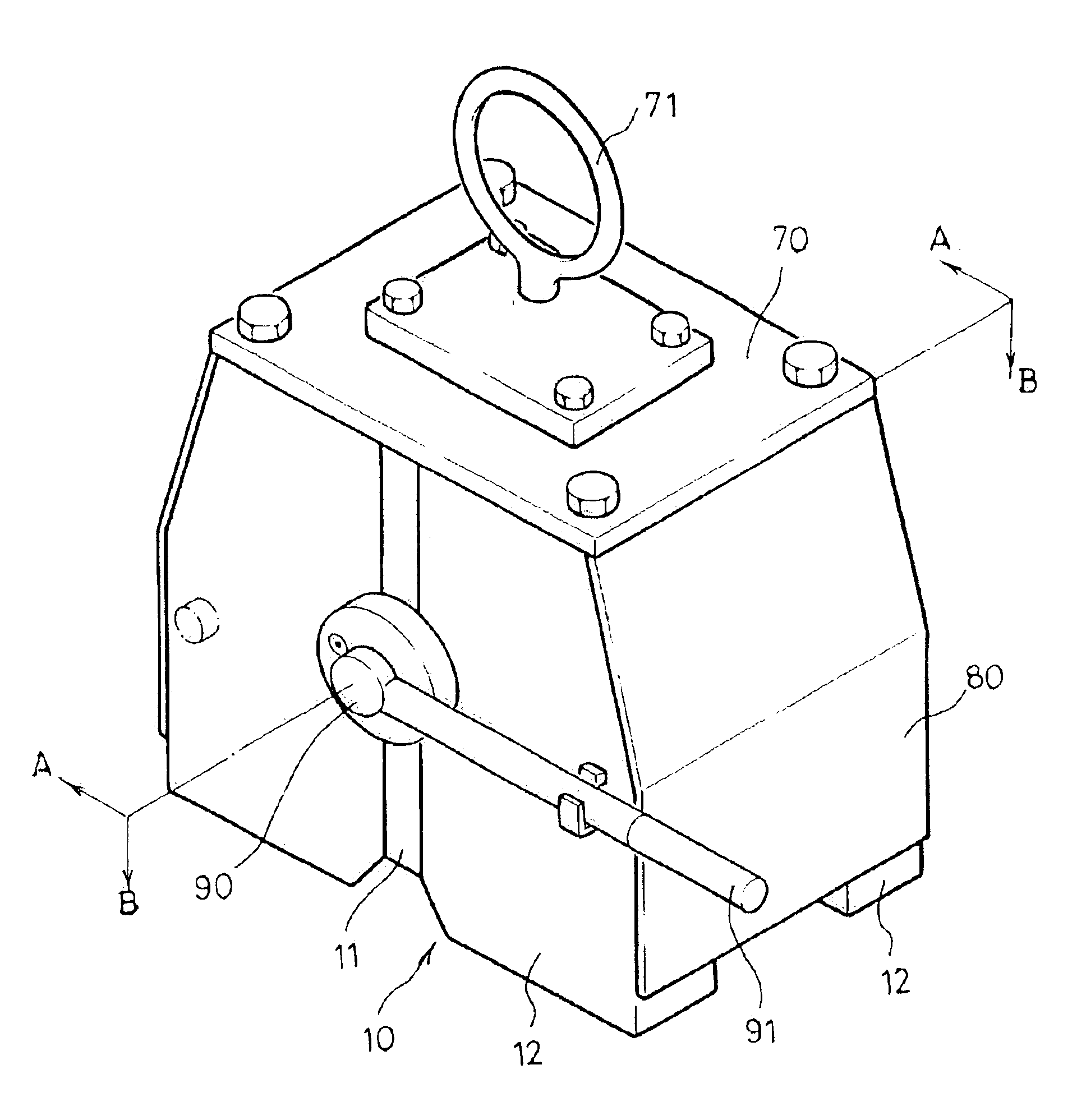
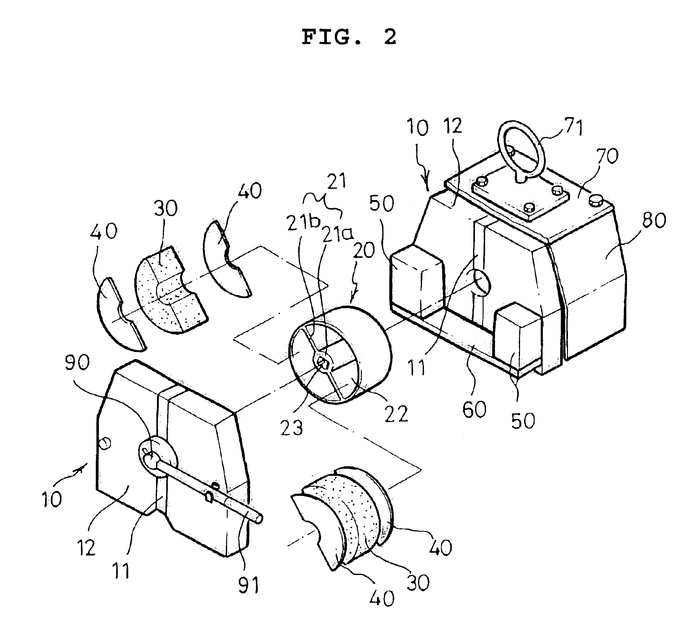
Referring to FIG. 7, the magnetic lifting machine according to the present invention will be described.

As all the constitutional parts of the magnetic lifting machine in the second and subsequent embodiments are the same as those in the first embodiment with the exception of means for fitting the anti-exfoliation plates into the rotor, reference numerals used in the first embodiment will also be used in the second and subsequent embodiments for identical parts of the machine, and description on the identical parts will be omitted.

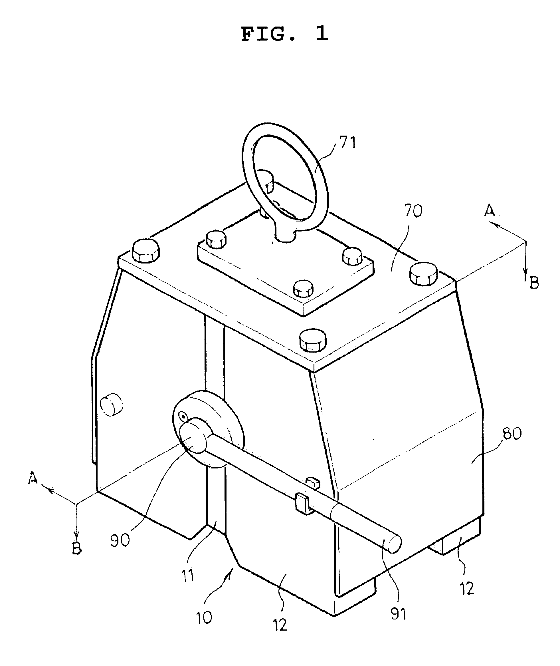
In the second embodiment, the rotor (20) is formed in the shape of a cylinder and has the central support (21) integrally formed along the diameter to divide the cylindrical rotor into two receptacles (22). The central support (21) in the second embodiment, however, is inwardly dented on both sides of the rotor (20) by the thickness of anti-exfoliation plates (41), and its thickness is the same as that of the neodymium magnets (30) fitted into the receptacl...

third embodiment

Referring to FIG. 9, the magnetic lifting machine according to the present invention will be described.

In the third embodiment, anti-exfoliation plate (42) are shaped in the form of a ring having the outside diameter slightly smaller than the inside diameter of the rotor (20) and the inside diameter slightly larger than the outside diameter of the boss (21a) of the central support (21). Each of the anti-exfoliation plates (42) has two concaved parts (42a) in opposite along the arms (21b) of the central support (21) of the rotor (20). In the center of each of the concaved parts (42a), a hole for bolt (42b) is formed.

The rotor (20) is formed in the shape of a cylinder and has the central support (21) integrally formed along the diameter to divide the cylindrical rotor (20) into two receptacles (22). The central support (21) has the boss (21a) in the center having the same thickness as the periphery of the rotor (20) and also has a pair of arms (21b), each of which is inwardly dented o...

fourth embodiment

Referring to FIG. 11, the magnetic lifting machine will be described.

In the fourth embodiment, anti-exfoliation plates (43) are shaped in the form of a ring having the outside diameter slightly larger than the outside diameter of the rotor (20) and the inside diameter slightly larger than the outside diameter of the boss (21a) of the central support (21). Each of the anti-exfoliation plates (41) has an extended flange (43a) along its periphery and two concaved parts (43b) in opposite along the arms (21b) of the central support (21) of the rotor (20). In the center of each of the concaved parts (43b), a hole for bolt (43c) is formed.

The rotor (20) is formed in the shape of a cylinder and has the central support (21) integrally formed along the diameter to divide the cylindrical rotor (20) into two receptacles (22). The central support (21) has the boss (21a) in the center having the thickness slightly larger than that of the periphery of the rotor (20) and also has a pair of arms (21...


PUM

PropertyMeasurementUnit
magnetic flux densityaaaaaaaaaa
magnetic performanceaaaaaaaaaa

Abstract

A magnetic lifting machine according to the present invention is to prevent an antioxidant film on the surface of neodymium magnets from exfoliation, by having the neodymium magnets not be in direct contact with a pair of polarity plates of the machine but via anti-exfoliation plates made of non-magnetic material. The anti-exfoliation plates are fitted to both sides of a rotor containing the neodymium magnets therein between the polarity plates, and each of the anti-exfoliation plates may include a plurality of holes for oil storage radially therethrough.

Description

FIELD OF THE INVENTIONThe present invention relates to a magnetic lifting machine using neodymium magnets, and more particularly to a magnetic lifting machine using neodymium magnets, which prevents an antioxidant film on the surface of a neodymium magnet from exfoliation, thereby improving magnetic performance and durability thereof.BACKGROUND OF THE INVENTIONConventionally, a magnetic lifting machine as disclosed in Japanese Utility Model Publication No. 1994-55206 comprises a pair of pole plates disposed to be opposite each other on both side ends of the machine and having a non-magnetic medium in the longitudinal center thereof and magnetic members on both sides of the non-magnetic medium; a cylindrical rotor axially supported to be rotatable between the pole plates; a pair of rotational permanent magnets inserted in the rotor and having its magnetic poles opposite to each other; and a pair of fixed permanent magnets disposed on both sides of the rotor. In such a conventional ma...

Claims


Application Information

Patent Timeline
Patent Type & Authority Patents(United States)
IPC IPC(8): B66C1/04B66C1/00
CPCB66C1/04
Inventor JUNG, HYUNG
Owner JUNG HYUNG
Why Eureka
Try Eureka