High capacity electrical terminal connection

a high-capacity, electric terminal technology, applied in the direction of multi-conductor cable end pieces, multi-conductor cable connectors, coupling device connections, etc., can solve the problems of affecting the service life of the terminal, so as to achieve the effect of reducing the possibility of thread damag

Inactive Publication Date: 2005-02-15
SAMSUNG ELECTRONICS CO LTD
View PDF12 Cites 28 Cited by
  • Summary
  • Abstract
  • Description
  • Claims
  • Application Information

AI Technical Summary

Benefits of technology

An object of the present invention is to overcome the above-described problems of the prior art. More specifically, an object of the present invention is to provide a mechanism for connecting first and second high capacity electric terminals to each other in a way that prevents the joined terminals from swinging relative to each other and from otherwise creating a risk of fire. Another object of the present invention is to provide a mechanism comprising a nut and a bolt for connecting first and second high capacity electric terminals to each other risk in a way that mitigates potential damage to the threads of the mechanism when the mechanism is tightened.

Problems solved by technology

Most of such equipment consumes a large amount of electric energy.
Most of the high capacity power cables are thick and heavy so that large amounts of electric power can be supplied therethrough.
Therefore, the terminal is often bent or broken when the nut and the bolt are tightened securely enough to connect the terminal of the power supply unit with the high capacity terminal of the power cable leading to the main power source.
Heat generated in this way eventually poses a fire risk.
Still further, the threads of the nut and bolt can be stripped when the nut and the bolt are tightened with excessive force.

Method used


Image

  • High capacity electrical terminal connection
  • High capacity electrical terminal connection
  • High capacity electrical terminal connection

Examples


Embodiment Construction

The first preferred embodiment of the present invention will now be described in detail with reference to FIG. 1 to FIG. 4.

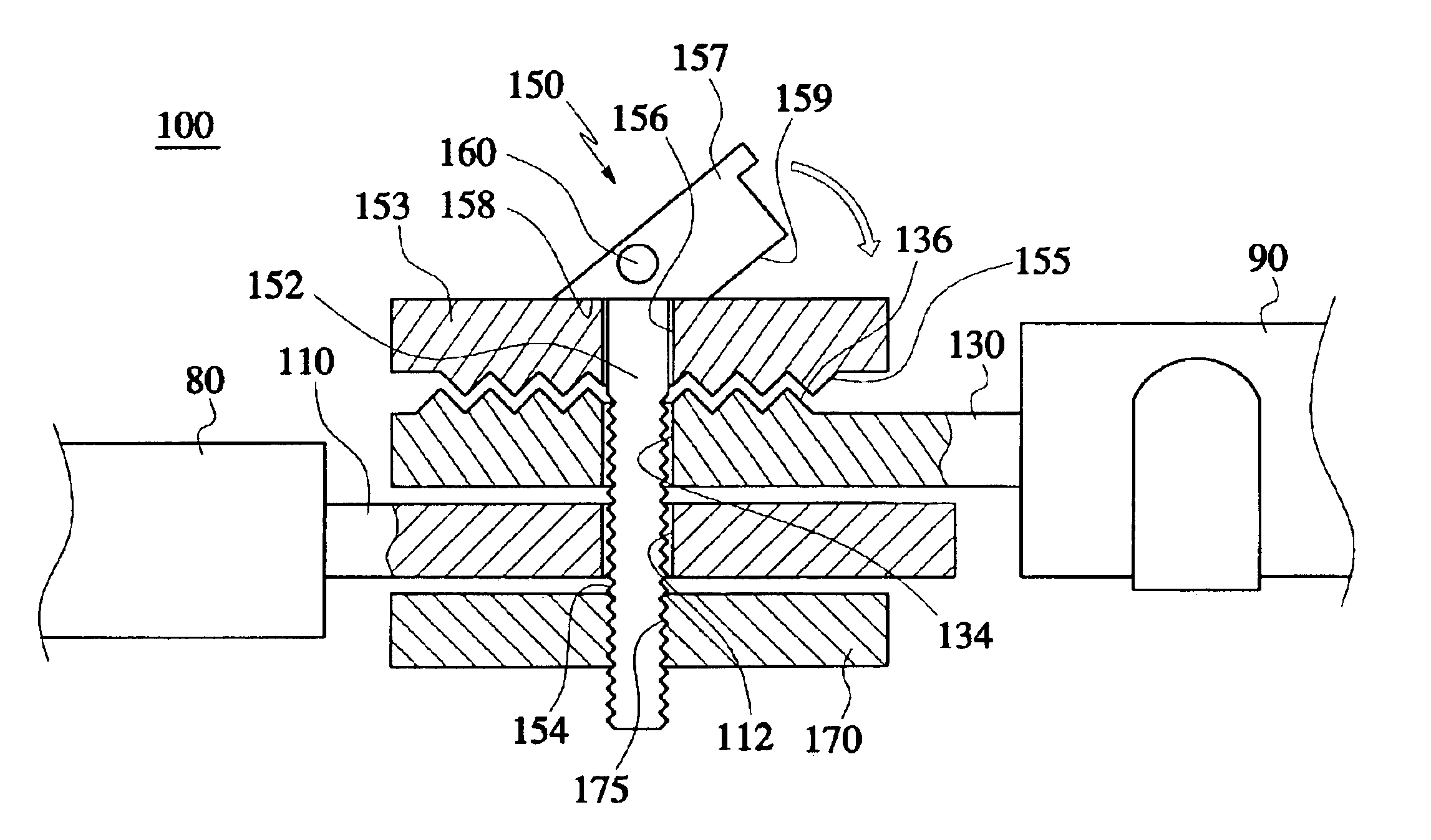
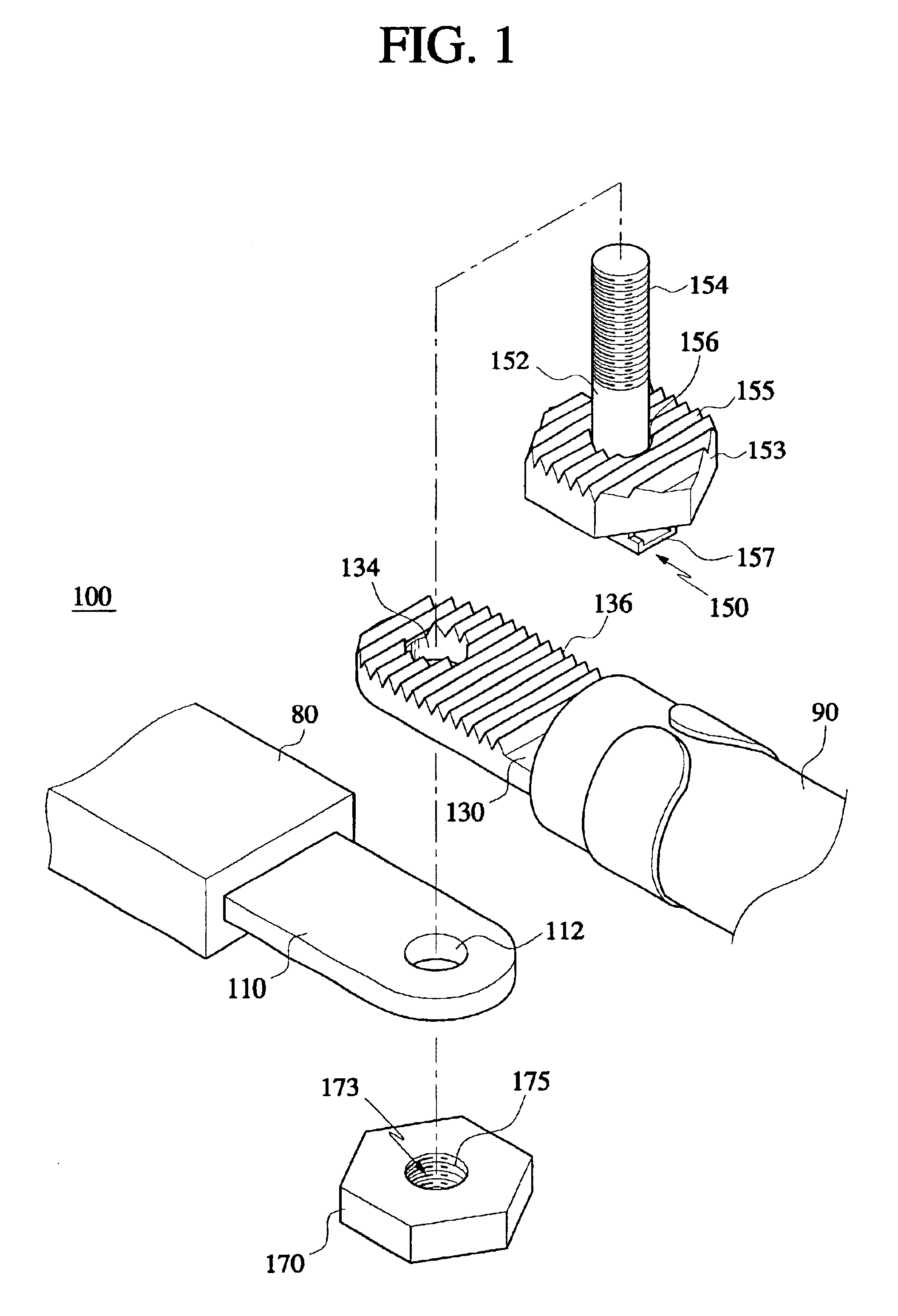
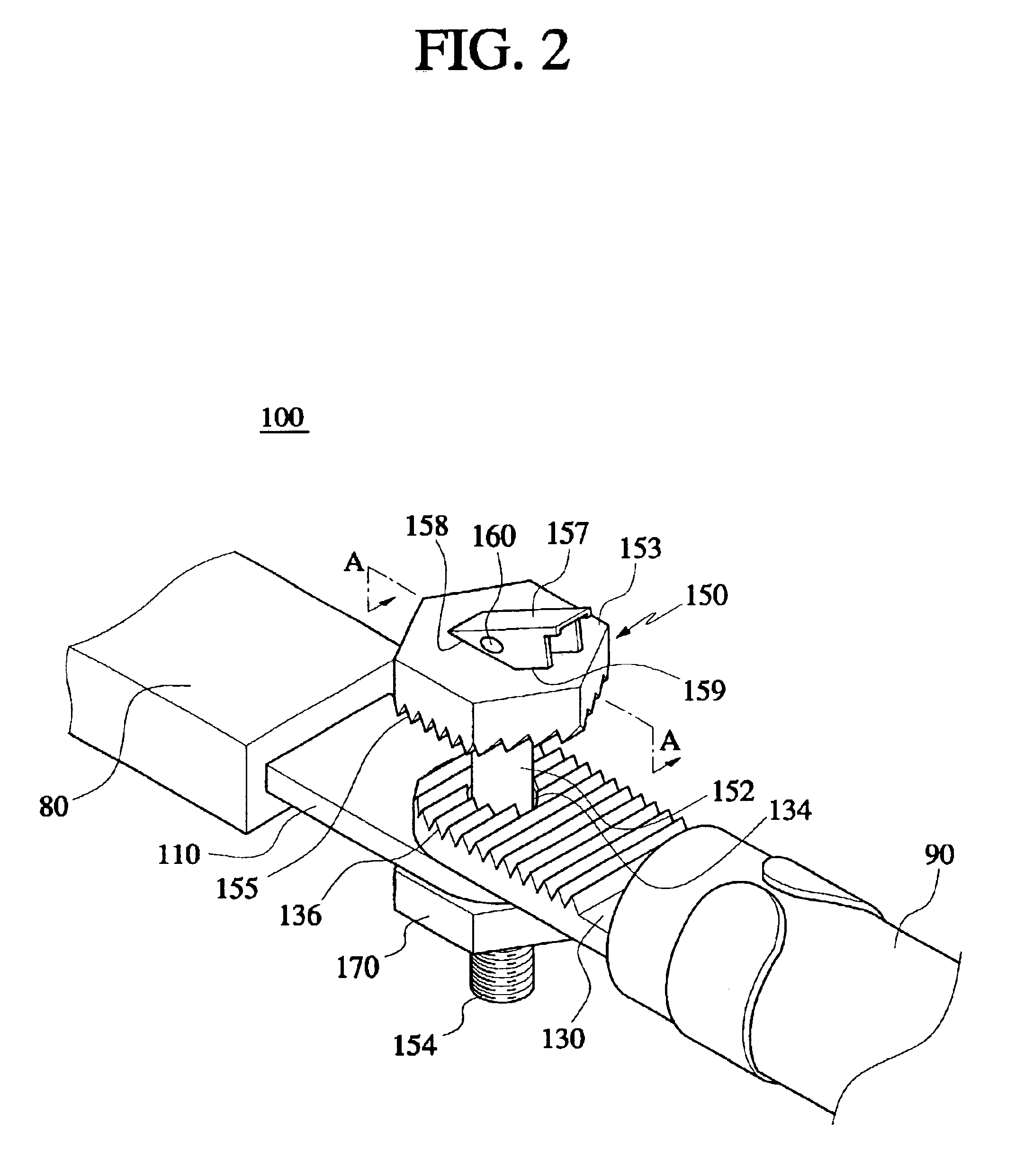
As shown in FIG. 1, the high capacity electric terminal connection 100 of the present invention comprises two terminals 110 and 130, a bolt unit 150 extending through the terminals 110 and 130, and a connection nut 170 connected with the bolt unit 150 to compressively fix the two terminals 110 and 130 together. The high capacity electric terminal connection 100 forms a tight joint between the first terminal 130 at the end of the high capacity power cable 90, and the second terminal 110 forming the terminal end of a power supply unit 80 of semiconductor device manufacturing equipment (not shown).

The bolt unit 150 comprises a bolt head 153, a bolt shaft 152, and a fixing bar 157. The bolt head 153 contacts and supports one side of one of the two terminals 110 and 130. On the other hand, the connection nut 170 contacts and supports a distal side of the other of the...


PUM


Abstract

The present invention provides a secure connection between first and second high capacity electrical terminals. A bolt unit extends through the first and second terminals and supports one side of the first terminal. A connection nut joined with the bolt unit supports a side of the second terminal remote from the first terminal. The side of the first terminal supported by the bolt unit has a surface including a first series of concavities and convexities. The side of the bolt unit in contact with the first terminal includes a second series of concavities and convexities engaged with the first series thereof. Therefore, it is difficult to pivot the joint created between the high capacity electric terminals. The bolt unit also includes a fixing bar that is pivotally supported by the shaft. The fixing bar can be rotated into a locking position to exert a compressive force on the joint.

Description

BACKGROUND OF THE INVENTION1. Field of the InventionThe present invention relates to the connecting of high capacity electric terminals. More particularly, the present invention relates to the structure that connects a power supply unit of semiconductor device manufacturing equipment to a power source.2. Description of the Related ArtIn general, various units of semiconductor device manufacturing equipment, such as photolithography equipment, ion-implanting equipment, thin film deposition equipment, and etching equipment, are used to perform respective unit processes in the manufacturing of a semiconductor device. Most of such equipment consumes a large amount of electric energy. Therefore, such semiconductor equipment is connected with high capacity power cables through which a large amount of electric power is supplied to the equipment.More specifically, a power supply unit supplies and distributes electric power to the various different units of the conventional semiconductor dev...

Claims


Application Information

Patent Timeline
Patent Type & Authority Patents(United States)
IPC IPC(8): H01R11/12H01R4/28H01R11/11H01R4/30H01R4/34H01R4/40H01R13/621H02B1/20H02G1/14H02G15/08
CPCH01R11/12H01R4/304H01R13/621
Inventor AN, HYEON-SU
Owner SAMSUNG ELECTRONICS CO LTD
Why Eureka
Try Eureka