Golf club with hosel cavity weight

a golf club and cavity weight technology, applied in the field of golf clubs, can solve the problems of not being able to adjust the hosel bore once the club head is in the weight pads that are integrally formed or attached inside the cavity of the golf club head, and the hosel bore cannot be fully formed or attached, so as to increase the moment of inertia of the club, increase the resistance of the club to twisting, and maximize the effect of the hos

Inactive Publication Date: 2005-02-15
KARSTEN MFG CORP
View PDF14 Cites 76 Cited by
  • Summary
  • Abstract
  • Description
  • Claims
  • Application Information

AI Technical Summary

Benefits of technology

The present invention comprises a metal wood-type golf club comprising a hollow body with a top wall, a bottom wall and a front wall configured for impacting a golf ball. The hollow body has a hosel bore disposed in the heel end behind the body front wall extending downwardly from an upper open end at the body top wall. According to one embodiment, a hosel bore weight is inserted into the bottom end of the hosel bore. Thereafter, the tip of a golf club shaft is inserted into the hosel bore and secured to the head to finish the club. The hosel bore weight may be chosen from a group of hosel bore weights of different mass. The hosel bore weights preferably comprise weights of substantially identical size and shape adapted to conform to the interior surface of the bottom end of the hosel bore. The mass of the hosel bore weights is adjusted by varying their density. According to one embodiment, the hosel bore weights comprise a polyurethane resin loaded with a powdered metal such as tungsten, copper or steel. The density of the cured polyurethane resin is varied by varying the type of metal and / or the quantity of metal suspended in the polyurethane resin. The hosel bore weights themselves have a unique ogival shape (an ogive being defined as a surface of revolution resulting from revolving an arc about an axis on the concave side of the arc). Locating the weight directly beneath the shaft tip maximizes the effectiveness of the hosel bore weight in increasing the moment of inertia of the club about the center of mass of the club, which increases the club's resistance to twisting when the ball is struck off-center. At the same time, the location of the hosel bore weight substantially along the axis of the shaft minimizes the increase in the moment of inertia about the shaft axis, which improves the speed at which the head comes around to a perpendicular position for impacting the golf ball. Moreover, by positioning the weight within the hosel bore, the weight can be selected after the head has been fully assembled (before installation of the shaft) allowing for the weight to be selected to optimize performance of the club head without affecting the external appearance of the club.

Problems solved by technology

Among the disadvantages of the aforementioned prior art patents, however, is that weight pads that are integrally formed or attached inside the cavity of the golf club head such as disclosed in Antonious and Rugge cannot be adjusted once the club head is assembled.
Conversely, externally attached inserts such as disclosed in Sun mar the appearance of the sole plate of the club and may come loose during use.

Method used


Image

  • Golf club with hosel cavity weight
  • Golf club with hosel cavity weight
  • Golf club with hosel cavity weight

Examples


Embodiment Construction

The drawing figures are intended to illustrate the general manner of construction and are not necessarily to scale. In the detailed description and in the drawing figures, specific illustrative examples are shown and herein described in detail. It should be understood, however, that the drawing figures and the detailed description are not intended to limit the invention to the particular form disclosed, but are merely illustrative and intended to teach one of ordinary skill how to make, and or use the invention claimed herein and for setting forth the best mode for carrying out the invention.

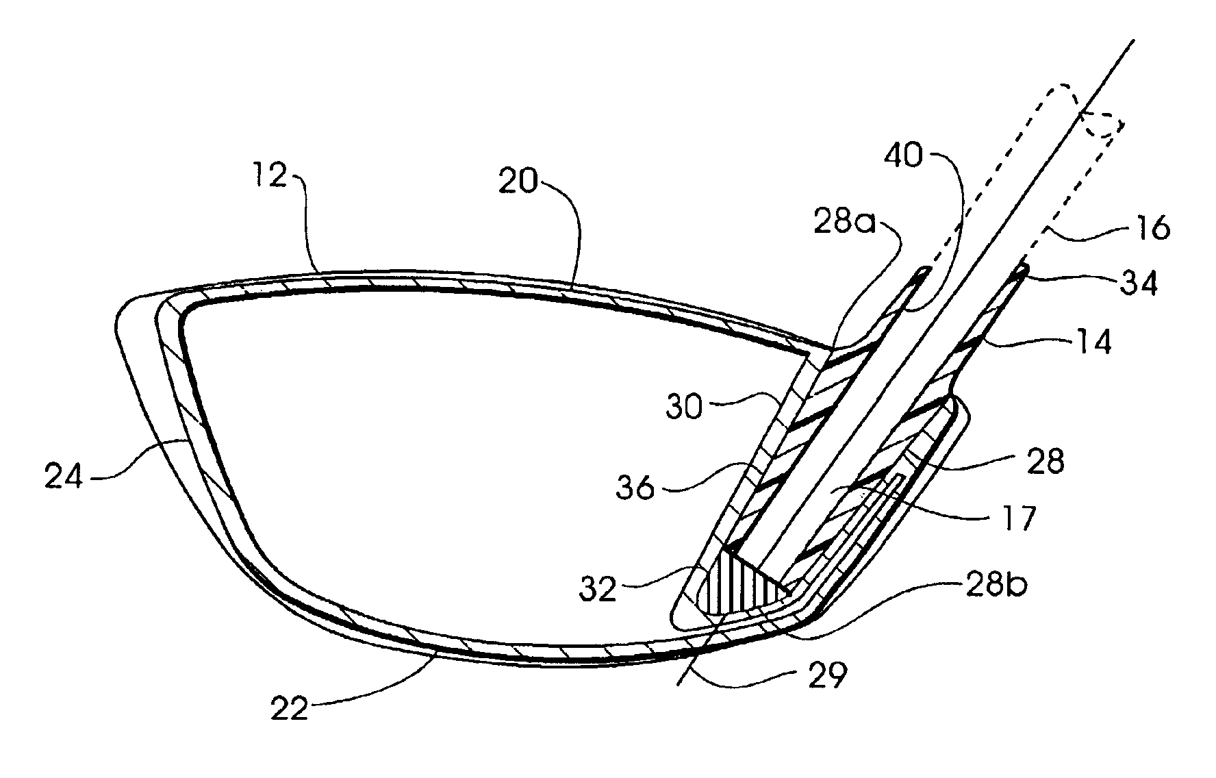
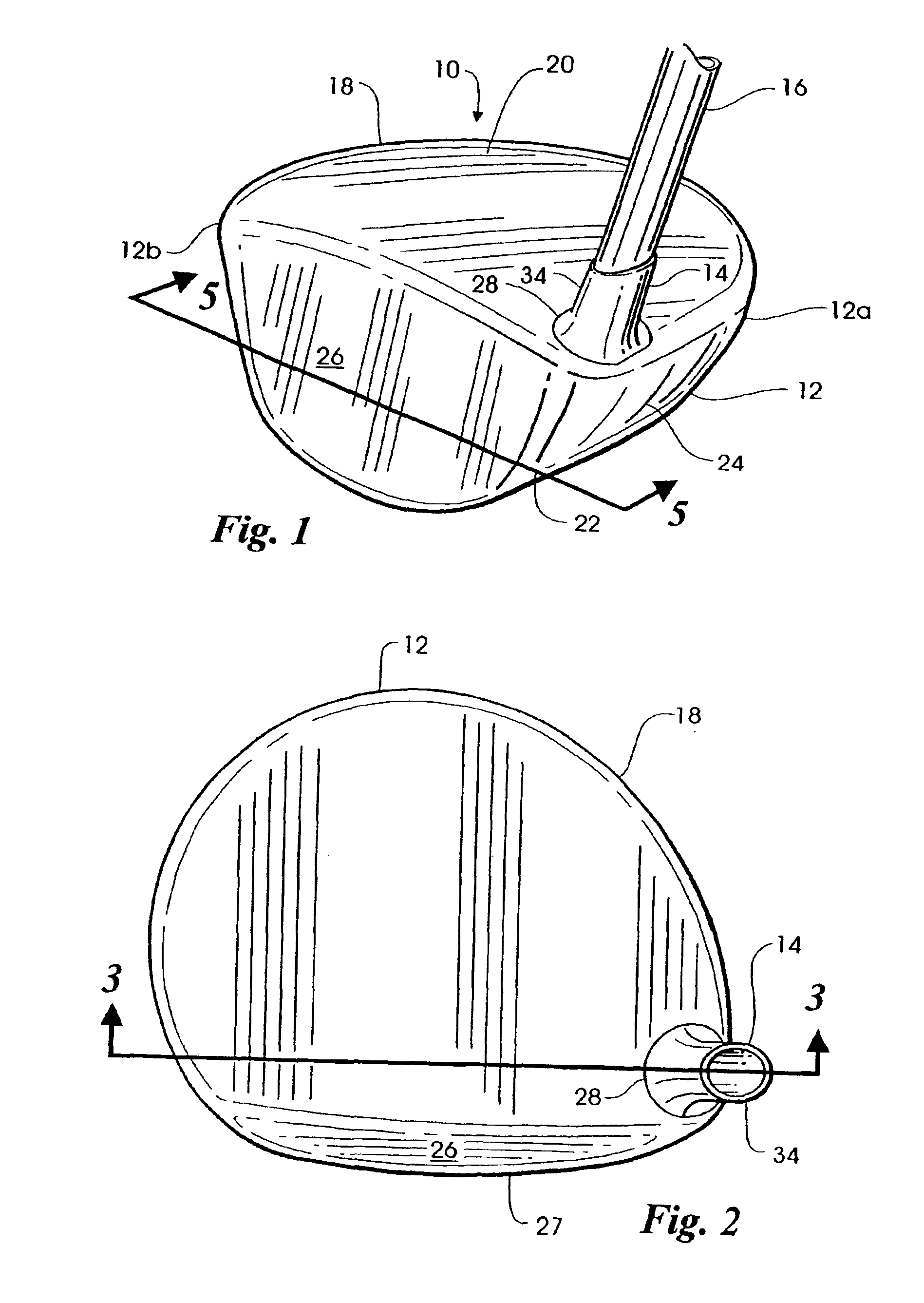
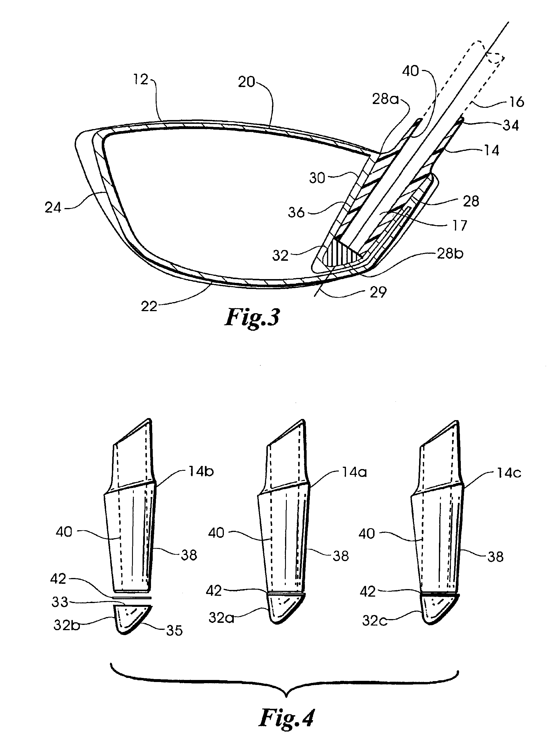
FIG. 1 depicts a golf club 10 comprising a head 12, a hosel 14 and a shaft 16. Head 12 is composed of a hollow body 18 made of a first material such as titanium having a high shear modulus of elasticity and a high strength to weight ratio. The hollow body 18 has a top wall 20, a bottom wall 22, and a side wall 24 connecting the top wall 20 to the bottom wall 22. Hollow body 18 has a front wall 2...


PUM


Abstract

A metal wood-type golf club has a hollow body with a hosel bore disposed in the heel end. A hosel bore weight, selected from a plurality of hosel bore weights of different mass, is inserted into the bottom end of the hosel bore. Thereafter, the tip of a golf club shaft is inserted into the hosel bore and secured to the head to finish the club. The hosel bore weights preferably comprise weights of substantially identical size and shape adapted to conform to the interior surface of the bottom end of the hosel bore with the mass of the hosel bore weights being adjusted by varying their density.

Description

BACKGROUND OF THE INVENTIONThis invention relates generally to golf clubs, in particular, to so-called metal wood-type golf clubs.Golf clubs known as “woods” traditionally have a head made of a suitable wooden material such as maple or persimmon attached to one end of an elongated shaft. These traditional wood club heads are usually solid and are shaped with their weight properly distributed about their center of gravity to maximize performance. Golf club “wood” heads have also been formed of suitable metals such as stainless steel and titanium. Metal wood heads are usually hollow so as to minimize weight while leaving the maximum amount of material available for the structural components of the head. Various attempts have been made to distribute weight in metal wood heads with respect to their centers of gravity so that the performance is maximized. Such attempts have included placing different types and numbers of weight members at different locations on or inside the metal heads....

Claims


Application Information

Patent Timeline
Patent Type & Authority Patents(United States)
IPC IPC(8): A63B53/04A63B53/02
CPCA63B53/02A63B53/0466A63B2053/0491A63B60/54
Inventor SOLHEIM, JOHN A.SANCHEZ, RICHARD R.
Owner KARSTEN MFG CORP
Why Eureka
Try Eureka