Intramedullary nail

Inactive Publication Date: 2005-02-15
SYNTHES USA
View PDF16 Cites 53 Cited by
  • Summary
  • Abstract
  • Description
  • Claims
  • Application Information

AI Technical Summary

Benefits of technology

The fact that the slot-shaped, elongated hole eliminates the angular rigidity in the direction of the longitudinal axis of the hip pin presents no drawback compared to prior art, since any rotation of the femoral head around the femoral-head screw remains inhibited by the hip pin which, after all, is and always will be the purpose of the hip pin. The use of an elongated hole for accepting the hip pin offers an advantage insofar as it permits mechanical load distri

Problems solved by technology

The smaller hip pin, because of its limited or even i

Method used


Image

  • Intramedullary nail
  • Intramedullary nail
  • Intramedullary nail

Examples


Embodiment Construction

For convenience, the same or equivalent elements in the various embodiments of the invention illustrated in the drawings have been identified with the same reference numerals. Further, in the description that follows, any reference to either orientation or direction is intended primarily for the convenience of description and is not intended in any way to limit the scope of the present invention thereto.

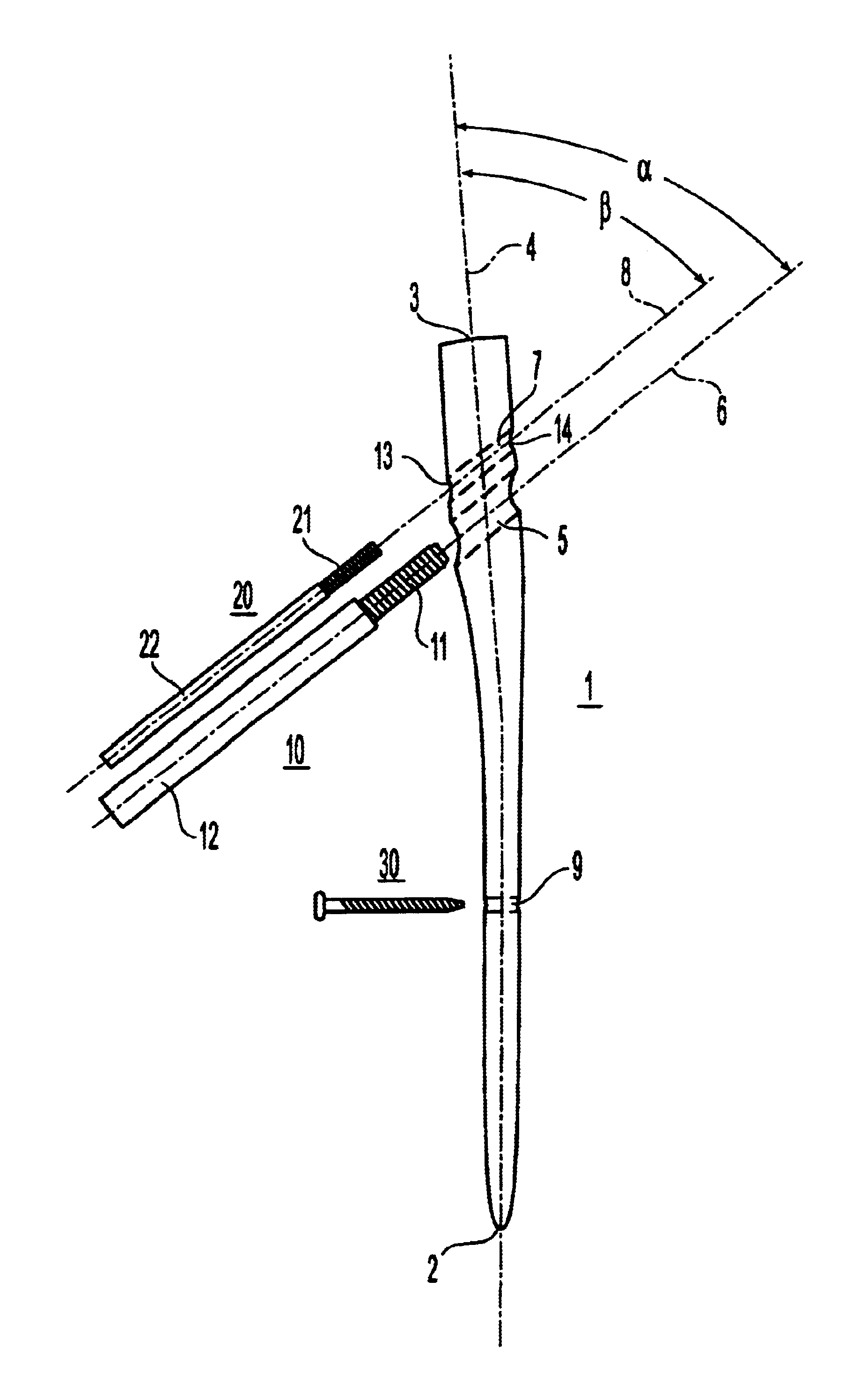
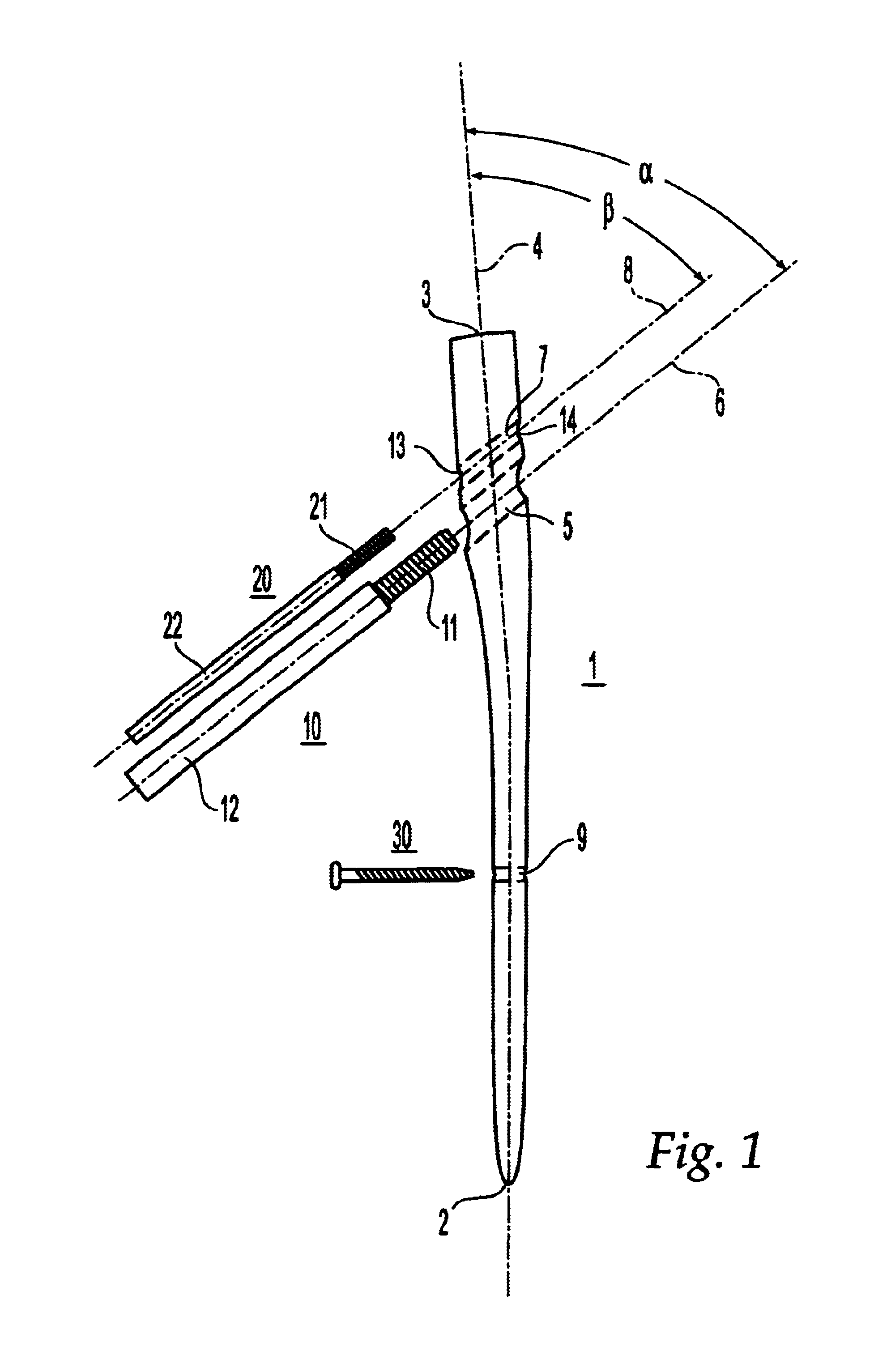
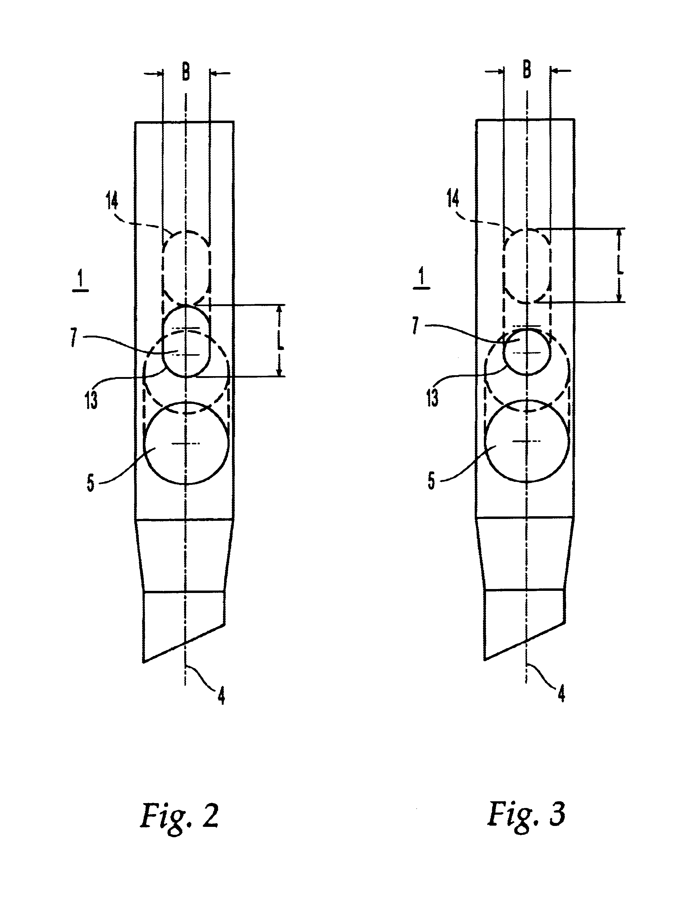
The intramedullary nail or intramedullary fastening pin 1 illustrated in FIG. 1, serving to stabilize femoral fractures, includes a distal end 2 intended for insertion in the medullary channel, a proximal end 3 and a longitudinal axis 4. Closer to its proximal end 3 and intersecting the longitudinal axis 4, the fastening pin 1 is provided with a first borehole 5, having a longitudinal axis or center line 6, designed to accept a hip screw 10. The center line 6 of the first cylindrically round borehole 5 extends at an angle α of 30° to 70° relative to the longitudinal axis 4, or an ang...


PUM


Abstract

The invention relates to an intramedullary nail used for treating fractures of the femur. It comprises a distal end, which is appointed for insertion into the marrow cavity channel, a proximal end, and a longitudinal axis. A first bore is located adjacent the proximal end and extends through the proximal end and transversely intersects the longitudinal axis, and serves to accommodate a femoral head screw. The center axis of the first bore forms an angle with the longitudinal axis that ranges from 110° to 150°. A second bore is located between the first bore and the proximal end and extends through the proximal end and transversely intersects the longitudinal axis, and serves to accommodate a hip pin. The second bore is at least partially shaped as an oblong hole or slot with a width B and a length L>B, and the length L of the oblong hole extends in the direction of the longitudinal axis.

Description

FIELD OF THE INVENTIONThe present invention relates generally to an intramedullary nailBACKGROUND OF THE INVENTIONAn intramedullary pin of this type has been described in EP-A 0 551 588. Its particular shortcomings consist of the fact that the two hip screws which are inserted in the head of the femur (femur-head screw and hip pin) extend through the circular openings in the intramedullary fastening pin in angularly rigid fashion. Due to their dimensionally defined difference in flexural strength it is possible during the clinical process for these two screws to move relative to each other. The smaller hip pin, because of its limited or even inhibited gliding ability, can penetrate the hip joint.SUMMARY OF THE INVENTIONThe present invention is directed to an intramedullary nail for the treatment of femoral fractures, comprising a distal end for insertion in the medullary channel, a proximal end, a longitudinal axis, and defining a first borehole located adjacent the proximal end ext...

Claims


Application Information

Patent Timeline
IPC IPC(8): A61B17/68A61B17/78A61B17/74A61B17/58
CPCA61B17/744
Inventor FRIGG, ROBERTBRUNNER, PETER
Owner SYNTHES USA
Why Eureka
Try Eureka