
Cable separator spline

a spline and separator technology, applied in the direction of insulated conductors, cables, conductors, etc., can solve the problems of undesirable skew degradation and less flexibility of the type of spline, and achieve the effect of good flexibility and acceptable next performan

Inactive Publication Date: 2005-02-15
BELDEN TECHNOLOGY INC
View PDF36 Cites 84 Cited by
  • Summary
  • Abstract
  • Description
  • Claims
  • Application Information

AI Technical Summary

Benefits of technology

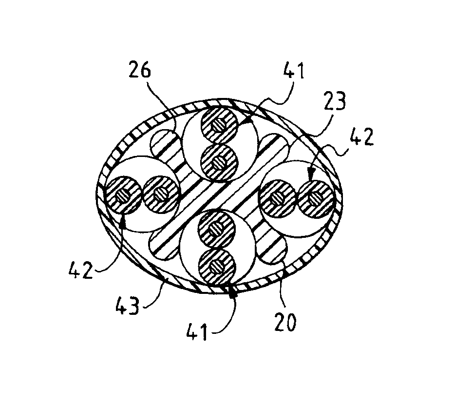
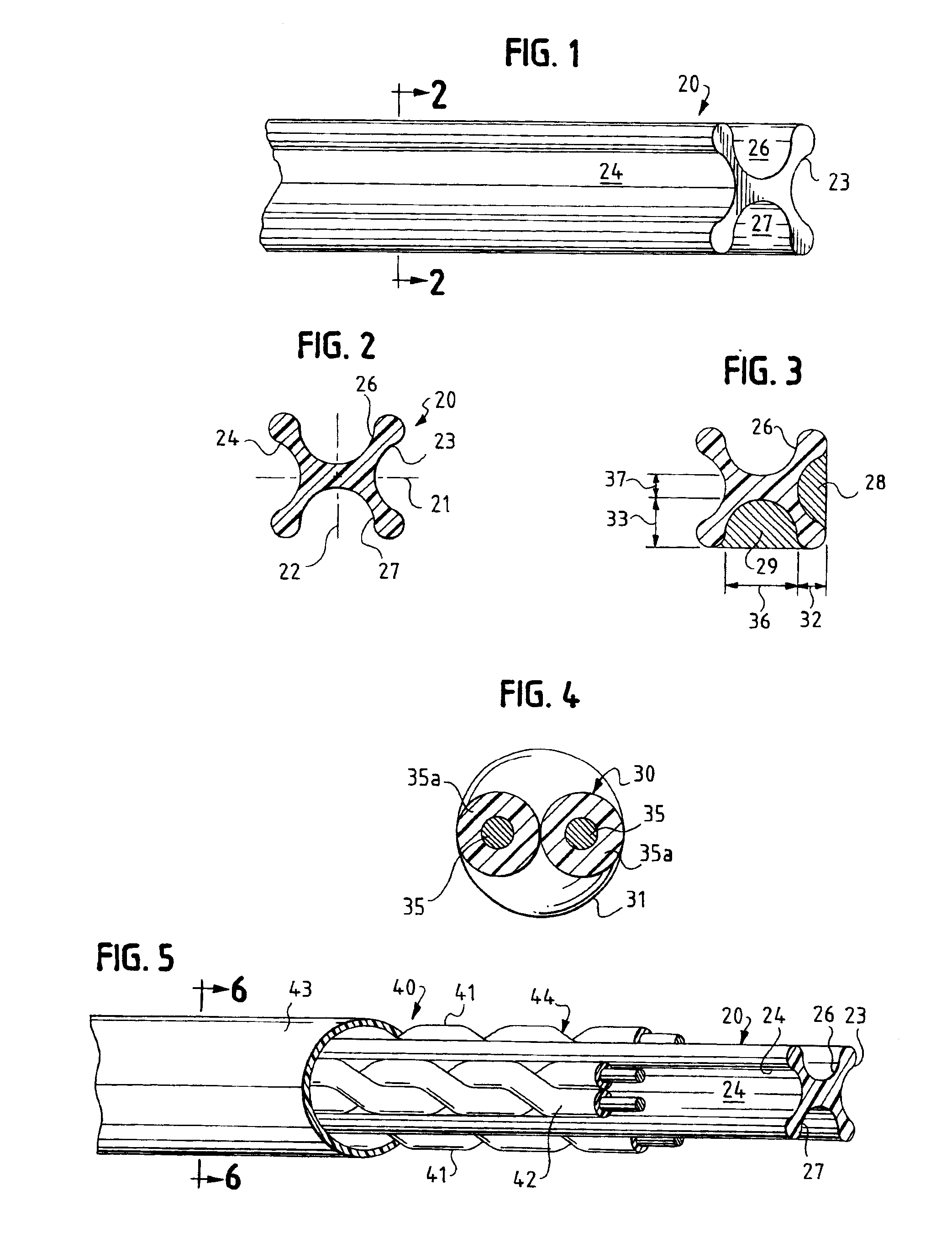
The oval envelope provided by my spline has an acceptable NEXT performance and good flexibility. Therefore, it is an object of the present invention to provide a cable separator filler or spline having a plurality and preferably four opened pockets for separating a plurality of cable pairs, preferably one cable pair for each pocket. Preferably when there are an even number of pockets, the pockets are diametrically opposite each other. When there are four pockets, the first and second pockets are diametrically opposite each other and third and fourth pockets are diametrically opposite each other. In a cross-sectional plane of the spline the diametric distance between the ends of the first and second pockets is greater than the diametric distance of the ends of the group of the third and fourth pockets to provide an oval envelope for the spline. All of the pockets have a cross-sectional area that is less than the envelope cross-sectional area of the cable pair that is to be placed in the respective pockets. The longitudinal axis of each of the pockets are all substantially parallel to each other.
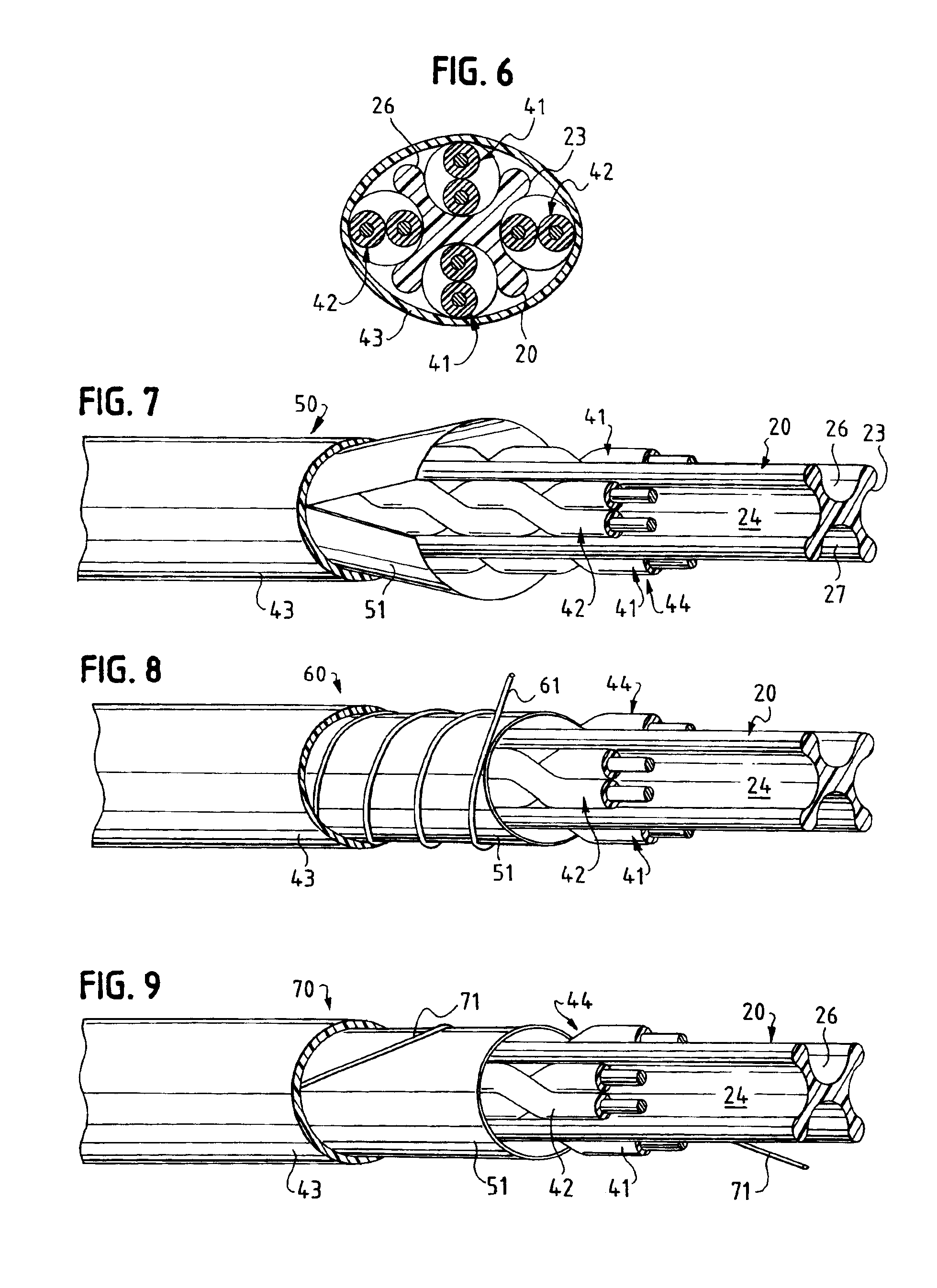
With my elongated separator spline long and short lay twisted pairs can be ideally placed for maximum electrical advantages. Short lay pairs, which have the best flexibility can be placed across the minor axis of the separator spline. Short lays typically have improved NEXT and the close proximity to one another does little to worsen NEXT. The long lay pairs can be placed across the major axis where bending strain is minimized. This overall cable design will bend across the minor axis based on the fact that the “column” will collapse across its minimum integral bending moment axis. The use of my elongated separator spline also improves skew over a similar round design because two unique cabling lay factors are in practice when the twisted pairs are cabled (minor and major axis). This helps compensate for the pair lengths between the long and short lay pairs equalizing the final conductor lengths which also tends to improve attenuation delta from the minimum lay pair to the maximum lay pair. My spline may be “metalized”, or coated with any form of metallic material that will preserve its exterior shape, and substantially improve NEXT while still enhancing the attenuation delta and skew of pairs.

Problems solved by technology

This type of spline generally has less flexibility and undesirable to skew degradation.

Method used


Image

  • Cable separator spline
  • Cable separator spline
  • Cable separator spline

Examples


Embodiment Construction

The following description taken in conjunction with the drawings will further explain the inventive features of my elongated separator spline and cables utilizing my elongated separator spline.

Referring to FIGS. 1 and 2, my elongated separator spline 20 has along its cross-sectional plane a major axis 21 and a minor axis 22. In the preferred embodiment, the minor axis 22 is perpendicular to the major axis 21. The preferred elongated separator spline 20 is shown with four cable pockets 23, 24, 26, and 27. Other oval configurations could have more or less pockets. The pockets 23 and 24 are on the major axis 21 and pockets 27 and 26 are on the minor axis 22. In a preferred embodiment, pockets 23 and 24 have the same cross-sectional area as each other and pockets 26 and 27 have the same cross-sectional area as each other. If desired, they can all have the same cross-sectional area. The cross-sectional area of the pockets are shown in FIG. 3. These are indicated by the shaded areas 28 an...


PUM


Abstract

A cable separator spline and a cable containing the cable separator spline in its core. The spline extends longitudinally and has a plurality of spaced longitudinally extending open pockets in which cables, such as twisted pair cables, can be placed and form part of the core. A cross-section of the spline has a major axis and a minor axis with the major axis being longer than the minor axis. At least one and preferably at least two pockets are on the major axis, and at least one and preferably at least two pockets are on the minor axis. The core containing the twisted pair cables in the pockets can of course be shielded and jacketed, just jacketed or any other desired cable construction that would benefit from the use of my elongated separator spline.

Description

FIELD OF THE INVENTIONThe present invention relates to a separator filler or spline. More particularly the present invention relates to the separator filler or spline having four pockets with each pocket having a cross-sectional area that is less than the envelope area of a pair of cables adapted to be placed in each pocket.BACKGROUND OF THE INVENTIONThe most popular separator fillers or splines are generally based on a circular cross-section wherein each pocket generally has a cross-sectional area that is greater than the cross-sectional envelope area of the twisted pair cable that is to be placed in the pocket. This type of spline generally has less flexibility and undesirable to skew degradation.SUMMARY OF THE INVENTIONThe oval envelope provided by my spline has an acceptable NEXT performance and good flexibility. Therefore, it is an object of the present invention to provide a cable separator filler or spline having a plurality and preferably four opened pockets for separating a...

Claims


Application Information

Patent Timeline
IPC IPC(8): H01B11/06H01B11/02H01B11/04
CPCH01B11/06H01B11/04
Inventor GAREIS, GALEN M.
Owner BELDEN TECHNOLOGY INC
Learn More