Device and method for SPR detection in a Mode-S transponder

a transponder and mode technology, applied in the field of avionics electronics, can solve the problems of aircraft not being able to detect spr signals within the collective received signal, existing transponders have met certain limitations, and are not properly receivabl

Inactive Publication Date: 2005-02-15
GARMIN INT
View PDF12 Cites 18 Cited by
  • Summary
  • Abstract
  • Description
  • Claims
  • Application Information

AI Technical Summary

Benefits of technology

Certain embodiments provide a method for controlling when a transponder replies to Mode-S interrogation signals. The method includes receiving Mode-S signals containing P5 and P6 pulses. The received P5 and P6 pulses have certain amplitudes. Each P6 pulse contains a sync phase reversal (SPR) signal followed by a data segment containing Mode-S data. The P5 pulse is asynchronous with respect to the P6 pulse and the P5 pulse is timed to overlay the SPR signal. The method further includes, analyzing each P5 and corresponding P6 pulse, and identifying the SPR signal correctly in at least 99% of the received Mode-S signals in which the amplitude of the P6 pulse is at least 12 dB greater than the amplitude of the P5 pulse and in no more than 2% of the received Mode-S signals in which the amplitude of the P6 pulse is at least 3 dB less than the amplitude of the P5 pulse, and replying to the Mode-S signals for which the SPR signal is correctly identified.

Problems solved by technology

However, existing transponders have met with certain limitations.
It is preferable that aircraft outside of the radar dish beam not reply as such communications unduly garble the transmission airspace and are not properly receivable by the radar dish.
In such cases, the aircraft is unable to detect an SPR signal within the collective received signal.
However, conventional transponders have experienced difficulty in correctly processing the P5 pulses and SPR signals in a manner that achieves proper cancellation.
This problem is further caused by the phase changes in the rising edge of the P5 pulse.
These phase changes will also cause the P5 pulse to jitter with respect to the SPR acceptance window.
As the P5 pulse jitters with respect to the SPR acceptance window within the circuits of the transponder, this reduces the ability of the P5 pulse to cancel out the SPR signal.
This timing error has caused conventional transponders to incorrectly identify SPR signals as valid, where such SPR signals should have been cancelled by the P5 pulse.
Conventional transponders experiencing the internal timing problems discussed above have difficulty in satisfying these reply standards.

Method used


Image

  • Device and method for SPR detection in a Mode-S transponder
  • Device and method for SPR detection in a Mode-S transponder
  • Device and method for SPR detection in a Mode-S transponder

Examples


Embodiment Construction

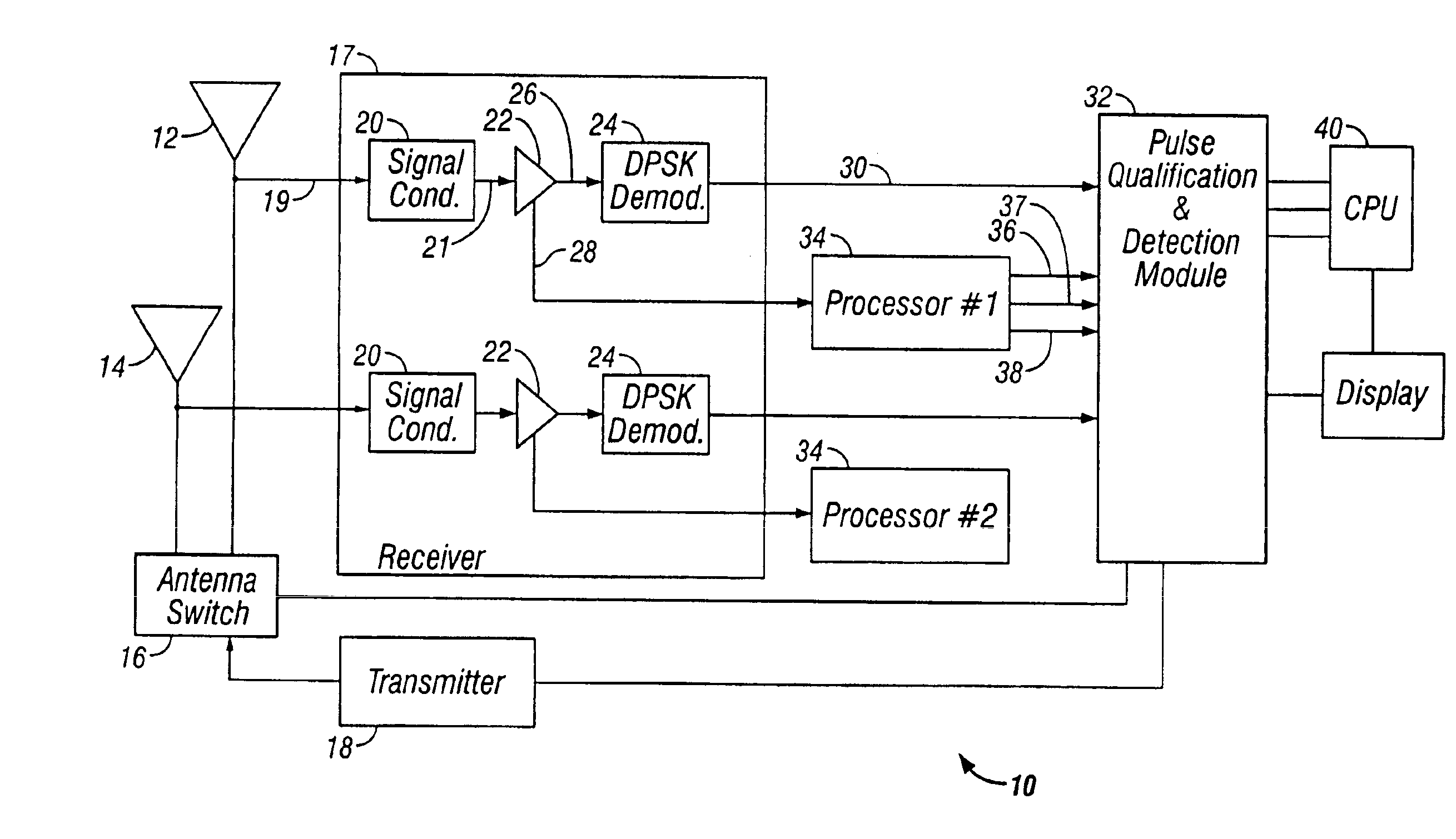
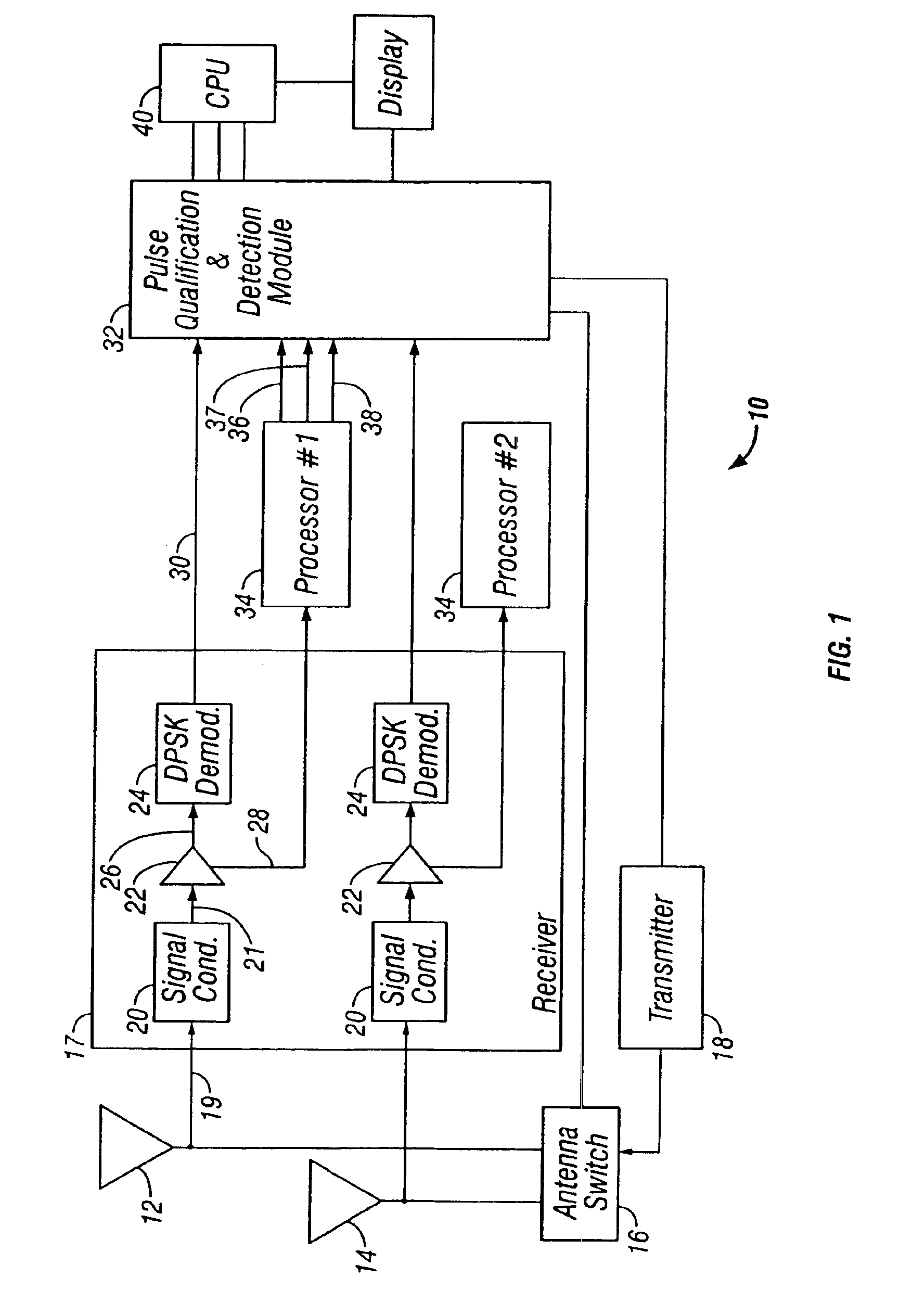
FIG. 1 illustrates a block diagram of a Mode-S transponder 10 formed in accordance with an embodiment of the present invention. The transponder 10 represents a diversity transponder in that it may be connected to first and second antenna 12 and 14 located on the top and bottom sides of an aircraft. One of the top and bottom antenna 12 and 14 is selected for use based upon one or more of several criteria such as received signal strength and which signal was received first. An antenna switch 16 selects one of the top and bottom antenna 12 and 14 based upon these criteria. A transmitter 18 outputs signals to be transmitted from the selected one of the top and bottom antenna 12 and 14. The receiver 17 communicates with processors 34 and a pulse qualification and detection module 32.

The top and bottom antenna 12 and 14 are connected to identical parallel receive channels, only one of which is described below in detail. Received signals 19 from the top and bottom antenna 12 and 14 are sup...


PUM


Abstract

A method is provided for controlling when a transponder replies to Mode-S interrogation signals. The method includes receiving Mode-S signals containing P5 and P6 pulses. The received P5 and P6 pulses have certain amplitudes. Each P6 pulse contains a sync phase reversal (SPR) signal followed by a data segment containing Mode-S data The P5 pulse is asynchronous with respect to the P6 pulse and the P5 pulse is timed to overlay the SPR signal. The method further includes, analyzing each P5 and corresponding P6 pulse, and identifying the SPR signal correctly in at least 99% of the received Mode-S signals in which the amplitude of the P6 pulse is at least 12 dB greater than the amplitude of the P5 pulse and in no more than 2% of the received Mode-S signals in which the amplitude of the P6 pulse is at least 3 dB less than the amplitude of the P5 pulse, and replying to the Mode-S signals for which the SPR signal is correctly identified.

Description

BACKGROUND OF THE INVENTIONThe present invention generally relates to avionics electronics. More specifically, the present invention relates to methods and devices for qualifying Mode-S signals and for controlling reply by transponders to Mode-S interrogations.A variety of transponders exist today for use with the Air Traffic Control Radar Beacon System (ATCRBS) and that support various communications protocols, such as Mode-C, Mode-A and Mode-S communication's protocols. ATCRBS ground stations, each have a rotating radar dish that transmits a beam having directional characteristics to transmit and receive information to and from aircraft within the relevant air space. The radar dish transmits over a common frequency to all of the aircraft. Each ATCRBS ground station also includes an omnidirectional antenna co-located with the directional radar dish. The omnidirectional antenna transmits, over a control frequency, among other things, side lobe suppression (SLS) signals which, as exp...

Claims


Application Information

Patent Timeline
Patent Type & Authority Patents(United States)
IPC IPC(8): G01S13/00G01S13/76
CPCG01S13/767G01S13/765
Inventor JOHNSON, TIMOTHY L.
Owner GARMIN INT
Why Eureka
Try Eureka