Remote examination of reactor nozzle J-groove welds

a technology of remote inspection and welds, which is applied in the direction of instruments, nuclear elements, greenhouse gas reduction, etc., can solve the problems of difficult implementation of precise robotic manipulation, difficult to achieve, and failure to teach nuclear reactor weld checking techniques inside the reactor

Inactive Publication Date: 2005-02-15
FRAMATOME ANP RICHLAND
View PDF8 Cites 26 Cited by
  • Summary
  • Abstract
  • Description
  • Claims
  • Application Information

AI Technical Summary

Benefits of technology

Still another aspect is to provide an easily understood

Problems solved by technology

The known testing equipment require a close proximity or actual contact to the tested weld surface which is difficult to achieve with the robotic delivery devices and the remotely controlled tools used to access the welds.
Thus some form of nondestructive remote testing of these welds was needed which did not require close proximity or contact with the welded surface and the exact robotic manipulation associated

Method used


Image

  • Remote examination of reactor nozzle J-groove welds
  • Remote examination of reactor nozzle J-groove welds
  • Remote examination of reactor nozzle J-groove welds

Examples


Embodiment Construction

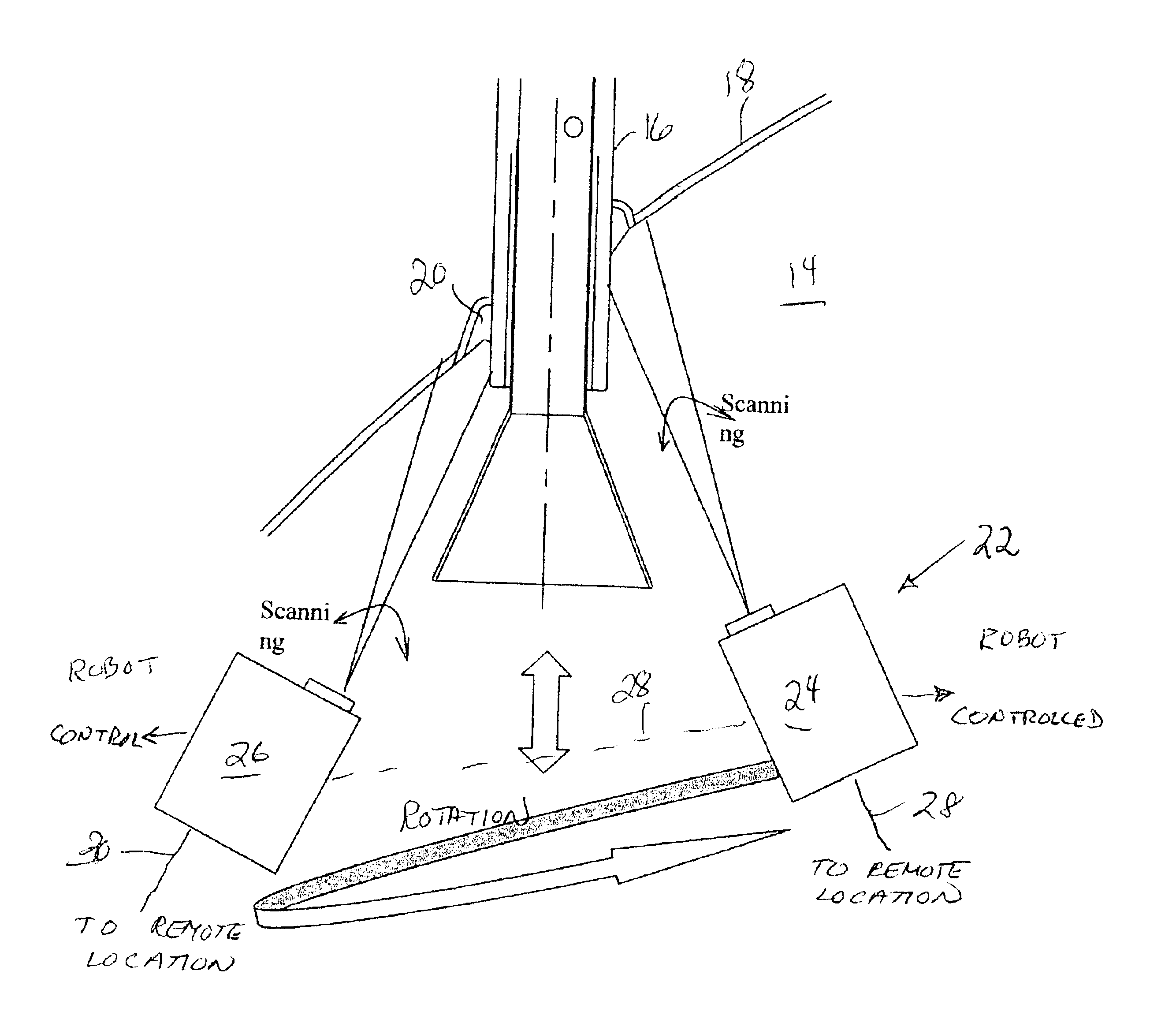
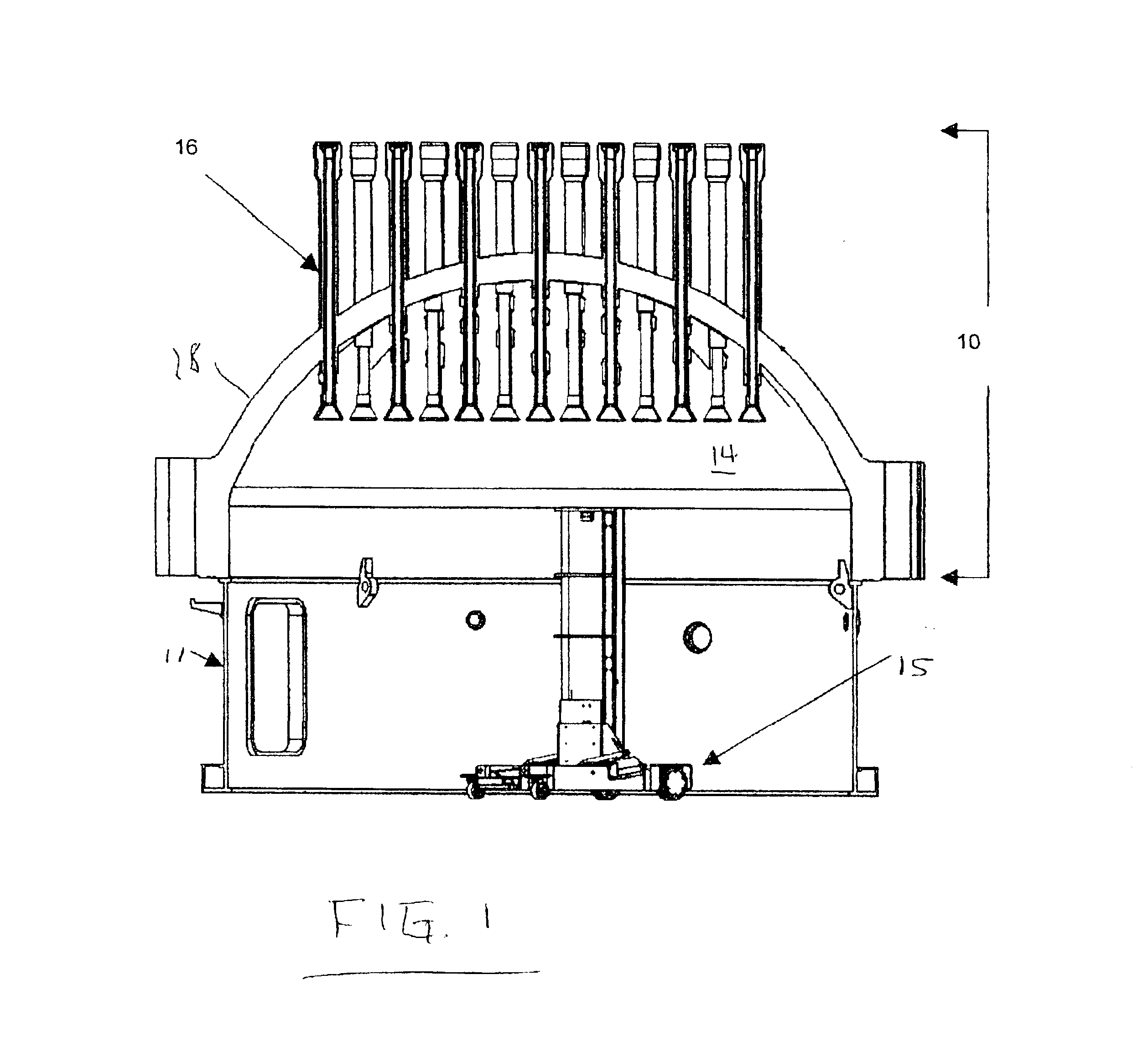
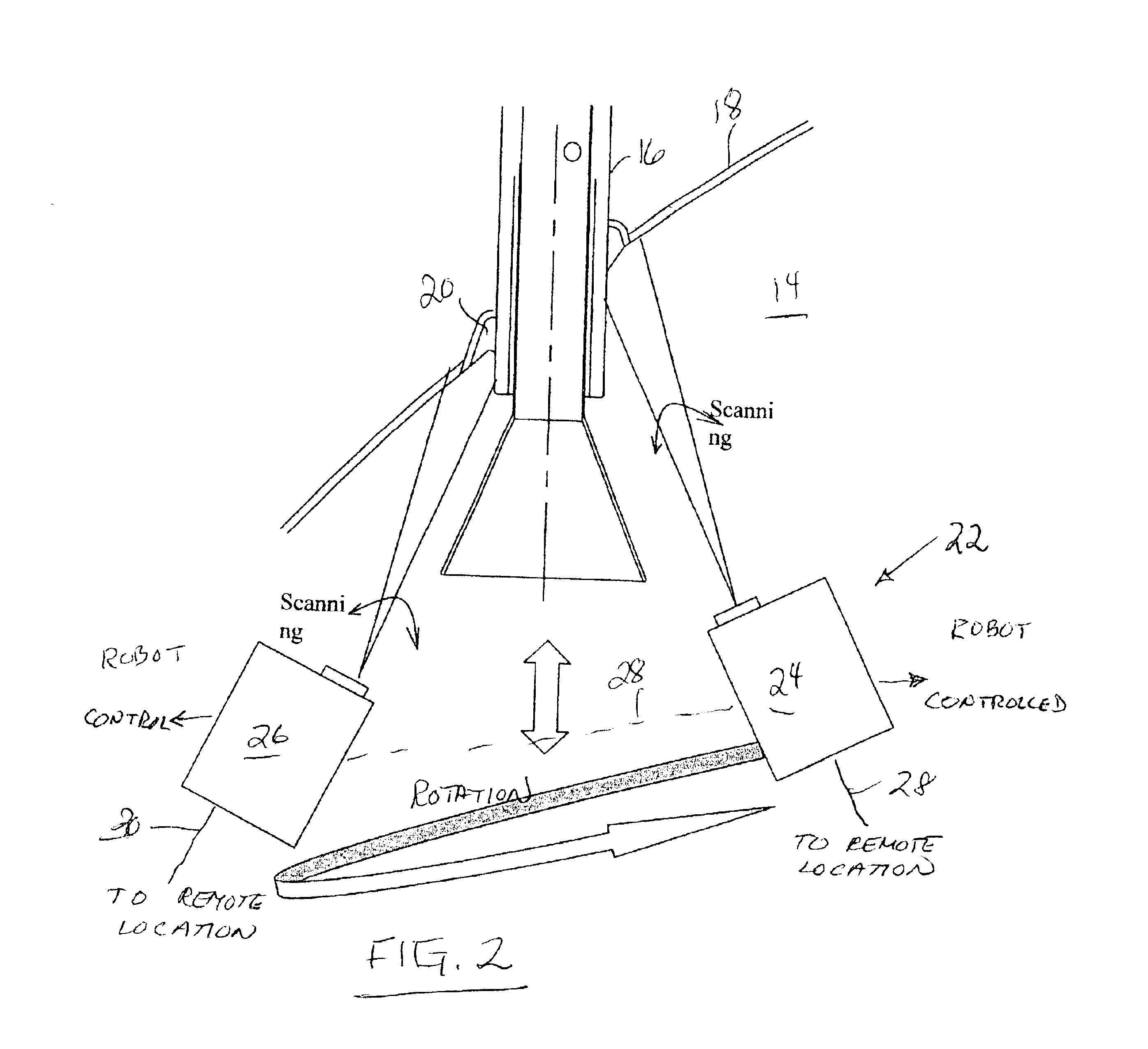
Referring now to the drawings, FIGS. 1 and 2 show a known nuclear reactor head assembly (10) on its refuel parking stand (11) having a series of Inconnel 600 control rod drive tubes (16) extending through the dome (14) of the reactor head (10). The carbon steel dome is clad with approximately 0.5 in. of stainless steel (18). The tubes are welded to the clad head (10) by a known J-groove weld (20). Under some conditions, the J-groove welds must be 100% inspected for flaws during reactor refuel and maintenance outages. This testing is done from beneath (14) the reactor head (10) by known robotics such as the ARAMIS or ROCKY robot (15) connected to testing assembly (22) which rotates the assembly (22) around the J-groove weld (20) from a location remotely spaced there from but sill offering a view of the weld (20).

The weld detection assembly (22) is comprised of a laser (24) which is aimed at a predetermined area of the weld (20) from a distance of around 0.5 to 1.5 meters and heats th...


PUM


Abstract

A combined laser and infra red sensing camera is located beneath the reactor head in the vicinity of the closure head tube welds by manipulating known robotic device handling the laser which is used to heat a line along the surface thereby generating a thermal wave that propagates over the one to two square inch test area where the increased thermal resistance of cracks and anomalies makes the surface temperature profile gradient greater at a crack or anomaly. An IR camera captures the test area image of interest as the thermal wave propagates across the target inspection area and the image is processed and enhanced to show cracks and other anomalies as a sharp drop in the thermal scan at the point of the crack using known Photo Thermal NDE technology to convert the scan into a pictorial representation of the scanned surface clearly showing any cracks therein. This process is repeated sequentially until the entire circumference of the weld is scanned.

Description

BACKGROUND OF THE INVENTION1. Field of the InventionThe present invention generally relates to photothermal inspection of surface welds and more particularly to remote phtothermal inspection of welds in reactor elements such as control rod nozzles.2. Description of the Prior ArtNuclear reactors have a reactor cover or closure head through which a series of openings having tubes extending into the inside surface of the reactor are welded to the closure head by J-groove welds. These tubes have control rod drives (CRD) and instrumentation packages sealably extending into the reactor internals. These J-groove welds must be inspected during reactor shut down for any cracks that may have developed in the welds. Such inspections must be made from beneath the reactor head with the head on a supporting head-stand during normal refueling periods. Standard nondestructive examination techniques such as eddy current and die-penetrant examinations are currently the normal inspection approach. Sin...

Claims


Application Information

Patent Timeline
IPC IPC(8): G21C17/003G21C17/017
CPCG21C17/003G21C17/017G21Y2004/40G21Y2002/304G21Y2004/30G21Y2002/20Y02E30/30
Inventor GLASS, SAMUEL W.CRISMAN, ELTON
Owner FRAMATOME ANP RICHLAND
Why Eureka
Try Eureka