Linear or rotary actuator

a technology of actuators and rotors, applied in the direction of bearings, shafts, dynamo-electric machines, etc., can solve the problems of unstable axial bearings, poor performance, and inability to use, and achieve the effects of not very expensive, reliable and efficien

Inactive Publication Date: 2005-02-22
SOC IND DE SONCEBOZ
View PDF6 Cites 30 Cited by
  • Summary
  • Abstract
  • Description
  • Claims
  • Application Information

AI Technical Summary

Benefits of technology

It is an object of the invention to realize an actuator that is efficient, reliable and not very expensive.
The partition wall may be made of an electro-conductive material such as a steel sheet that on one hand is strong and inexpensive and on the other hand ensures an electric and physical separation of the motor part from the screw and nut mechanism.

Problems solved by technology

This axial bearing is not very rigid and performs poorly owing to friction.
A device such as that described in EP-A-468 920 cannot be used, since the separation between motor and screw is insufficient.
The axial and radial support of the nut is very loose and thus unstable, both with respect to static and with respect to dynamic forces.
The reliability of sealing thus depends on the quality of the seal, which may deteriorate with time, may move when exposed to impacts, or may be poorly installed, for instance at the time of manufacturing of the motor.

Method used


Image

  • Linear or rotary actuator
  • Linear or rotary actuator
  • Linear or rotary actuator

Examples


Embodiment Construction

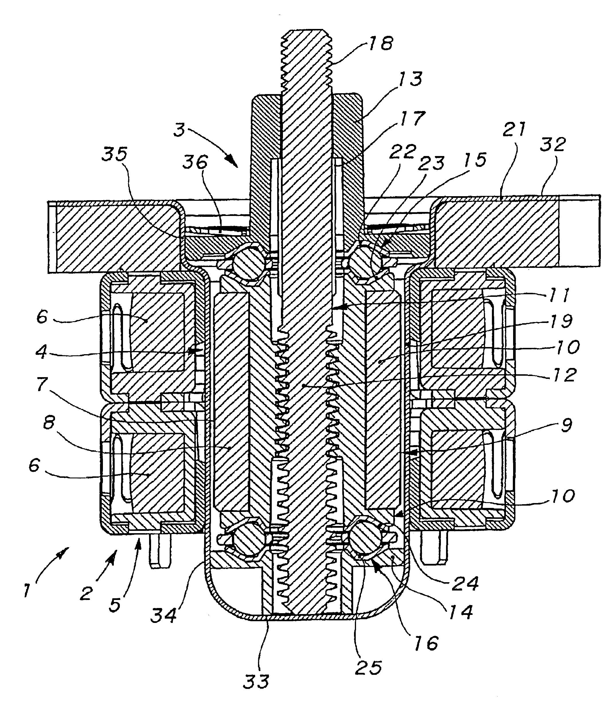
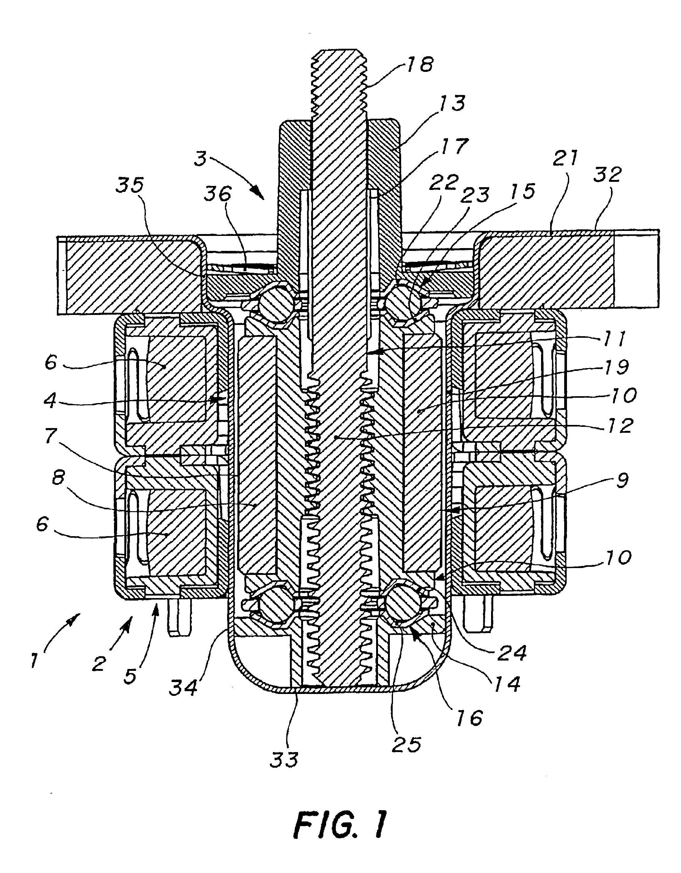
Referring now to FIG. 1, an actuator 1 comprises an electric motor part 2, an actuating part 3 and a partition wall 4. The electric motor part 2 in these examples comprises a step motor having aspects similar to those of conventional step motors, such as the stator 5 with two portions 6 with coils separated by an air gap 7 of permanent magnets 8 mounted on a rotary member 9 of the actuating part 3. The use of a step motor is advantageous inasmuch as it allows an easy, rapid setting of the position of the member to be controlled in a compact, not very expensive design. Nevertheless, other types of reversible motors may be used in the present invention.

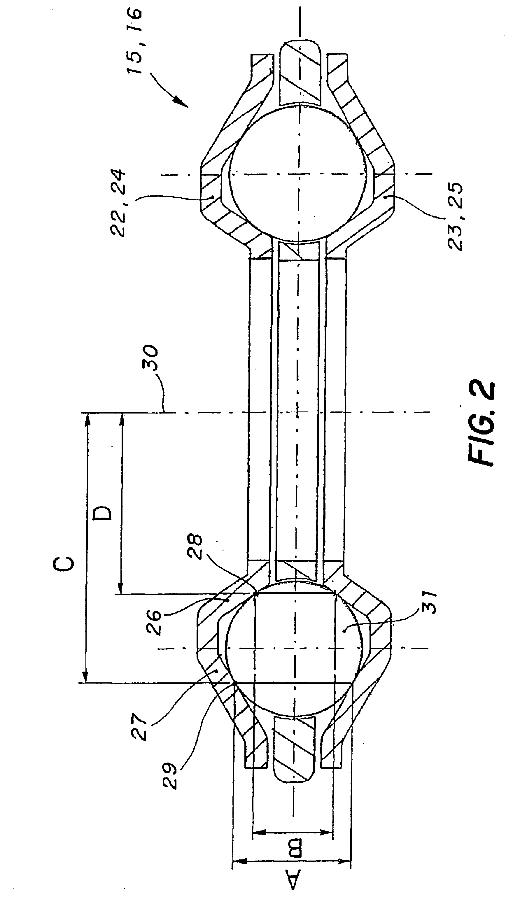
The actuating part 3 comprises the rotary member 9 provided with a threaded portion 10 engaging with a matching member in the form of a screw 11 having a threaded portion 12, a cover part 13, a housing part 14 and bearings 15, 16 supporting the rotary member 9 when rotating.

In the embodiment illustrated, rotation of the rotary member 9 ...


PUM


Abstract

An actuator (1) for the linear displacement of a member to be controlled comprising a motor part (2) and an actuating device part (3) including a threaded screw (11) with linear displacement, and a rotary member (9) provided with a threaded portion (10) matching the screw thread, the rotary member capable of being driven in rotation by the motor part and being supported by bearings (15,16) in the form of roller bearing stops with four contact points arranged on either axial side of said threaded portion to guide the rotary member axially and radially. The raceways of the balls are directly in the rotary member and integral with parts of the body (14) or the cover (13) of the actuator.

Description

The present invention concerns a linear or rotary actuator comprising a member rotated by an electric motor for the displacement of a member to be controlled. The member may more particularly be a nut in a screw and nut mechanism for the linear displacement of a member to be controlled.BACKGROUND OF THE INVENTIONLinear actuators are very common and are used in many different applications, with examples being described in the European patent applications EP-A-468 920 and EP-A-987 477. The devices described in these publications comprises a step motor driving a screw and nut mechanism for the linear displacement of a shaft integral with a screw. The step motor allows the screw shaft to be rapidly displaced and positioned with few mechanical carts and using relatively simple controls.In EP-A-468 920, a pinion mounted on the motor axle engages with a wheel that is integral with the nut. A hub of the wheel is sandwiched between flanges of a housing for axial positioning of the wheel. Thi...

Claims


Application Information

Patent Timeline
Patent Type & Authority Patents(United States)
IPC IPC(8): F16C19/02F16C19/16H02K7/06H02K5/12H02K5/128F16C19/10
CPCF16C19/10F16C19/166H02K7/06H02K5/128Y10T74/18664Y10T74/18712F16C33/588F16C2380/27F16H25/20
Inventor PFISTER, JEAN-FRAN.CEDILLA.OIS
Owner SOC IND DE SONCEBOZ
Why Eureka
Try Eureka