Methods, apparatus and products useful in the operation of a sucker rod pump during the production of hydrocarbons

a technology of sucker rod pump and sucker rod, which is applied in the field of methods, products and products for the production of hydrocarbons with sucker rod pumps, can solve the problems of damage to the pumping system, general cost of maintenance, and high cost of repair labor and parts

Inactive Publication Date: 2005-02-22
RAVDOS HLDG INC
View PDF12 Cites 43 Cited by
  • Summary
  • Abstract
  • Description
  • Claims
  • Application Information

AI Technical Summary

Benefits of technology

It is even another object of the present invention to provide for apparatus, methods, and products for monitoring and / or operating a reciprocating well, which allow for the concurrent viewing of the surface card and the downhole card.

Problems solved by technology

While sucker rod pumps are relatively simple units, they are generally expensive to provide and maintain.
This repair is costly in terms of repair labor and parts cost, and in the terms of lost revenue from the well.
This can cause harm to the pumping system such as broken rods or damage to the drive unit or downhole pump.
Unfortunately, these simple clock timers are not responsive to changing conditions, such as changes in the reservoir, or the occurrence of abnormal operating conditions.
These abnormal conditions of sucker rod pump operation can also be detrimental to the pump, and the well efficiency, and many of these abnormal conditions can be detected by accurate monitoring of the pump operation.
The decrease in power will result in a decrease in the area of the surface dynamometer card.
A common shortcoming of the beam-mounted strain gauges is the inability of the strain gauges to differentiate between strain caused by load on the beam or metal and strain caused by changing temperature of the metal.
This problem is particularly noticeable when the strain gauge is mounted on the beam rather than the polish rod.
Because these systems eventually zero out all changes, the absolute level of load is never known, and even the load relative to a datum is not known.
A major disadvantage of all of these “surface card” methods, is that the surface card is not always an accurate representation of the downhole rod string displacement (or position) and the downhole load on the rod string.
Use of the surface card introduces errors caused by ambiguities in the surface card, the obscuring effects of downhole friction along the rods, as well as numerous other factors.
As these measurements are not possible to easily obtain, methods exist to estimate this downhole card.

Method used


Image

  • Methods, apparatus and products useful in the operation of a sucker rod pump during the production of hydrocarbons
  • Methods, apparatus and products useful in the operation of a sucker rod pump during the production of hydrocarbons
  • Methods, apparatus and products useful in the operation of a sucker rod pump during the production of hydrocarbons

Examples


Embodiment Construction

The present invention will be described by reference to the drawings.

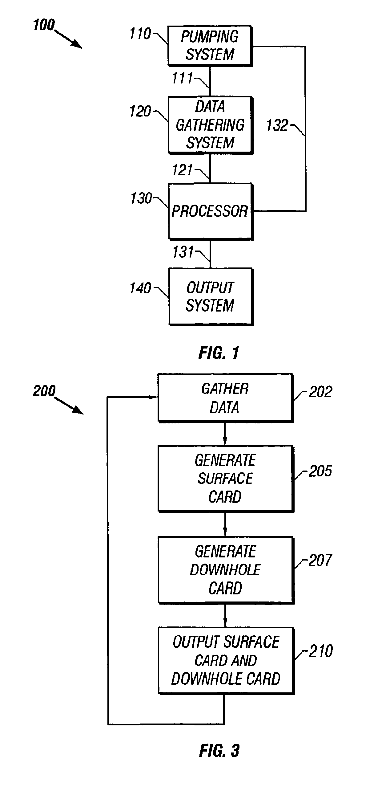
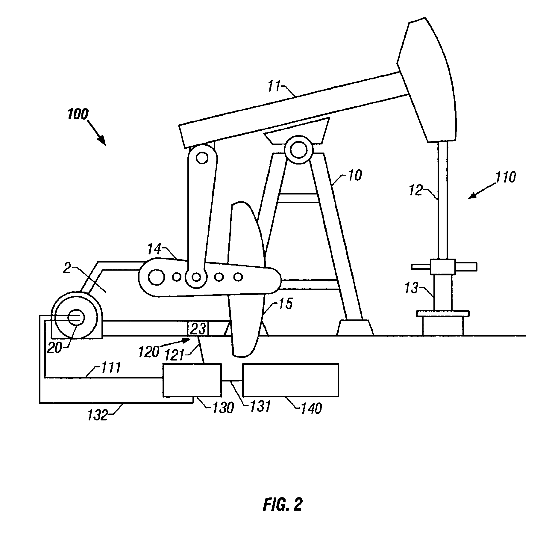
Referring first to FIG. 1, there is shown a schematic representation of well unit 100 of the present invention, including pumping system 110, data gathering system 120, processor 130, and output system 140.

Data gathering system 120 is in communication with pumping system 110 and processor 130, by communication link 111 and communication link 121, respectively. Processor 130 is in communication with output system 140 by communication link 131, and optionally in communication with pumping system 110 by communication link 132. It should be understood that communication links 111, 121, 131 and 132 can be physical wire links or may be wireless links. These links may include one or more types of links, for example, phone line, network, Internet, and wireless.

It should also be understood that while data gathering system 120, processor 130, and output system 140 are shown as separate boxes in FIG. 1, any two, or perhaps al...


PUM


Abstract

Apparatus, methods and products for monitoring / controlling a reciprocating well producing hydrocarbons from a wellbore, which determine the surface card from a well operating characteristics, determine the downhole card, and display both at the same scale for position.

Description

BACKGROUND OF THE INVENTION1. Field of the InventionThe present invention relates to apparatus, methods and products for the production of hydrocarbons. In another aspect, the present invention relates to methods, apparatus and products for the production of hydrocarbons with sucker rod pumps. In even another aspect, the present invention relates to methods, apparatus and products useful in the operation of a sucker rod pump during the production of hydrocarbons.2. Description of the Related ArtHydrocarbons are often produced from wellbores by sucker rod pumps.These “sucker rod” pumps are reciprocating pumps driven from the surface by pumping units that move a polished rod up and down through a packing gland at a wellhead. The unit may be of the predominant beam type or any other type that reciprocates the polished rod. For example, a beam pumping unit utilizes a walking beam pivotally mounted on a Samson post with one end of the beam being attached to the rod and with the beam bein...

Claims


Application Information

Patent Timeline
Patent Type & Authority Patents(United States)
IPC IPC(8): G05B23/02E21B47/00
CPCE21B47/0008E21B47/009
Inventor BRAMLETT, BOBBY R.DORADO, DONEIL M.GIBBS, SAM GAVINNOLEN, KENNETH BERNARDBOYER, LEMOYNE
Owner RAVDOS HLDG INC
Why Eureka
Try Eureka