Axial thrust bearing

a technology of axial thrust bearing and axial thrust bearing, which is applied in the direction of bearings, shafts and bearings, rotary bearings, etc., can solve the problem that the type of thrust bearing cannot be pre-manufactured as a complete structural unit, and achieve the effect of simple and cost-efficient installation, simple

Inactive Publication Date: 2005-02-22
INA SCHAEFFLER KG
View PDF17 Cites 37 Cited by
  • Summary
  • Abstract
  • Description
  • Claims
  • Application Information

AI Technical Summary

Benefits of technology

According to another feature of the present invention, there may be provided a resilient clamping ring for acting upon the other one of the outer running disks in an axial direction, wherein the clamping ring is supported on the sleeve. In this way, the thrust bearing can be assembled in a particularly simple manner. Suitably, the clamping ring is made of a material which is harder than a material of the sleeve. As a result, the resilient clamping ring can dig into the sleeve, just like a knife, to thereby provide for a secure axial union of the unitary structure.
According to another feature of the present invention, the middle running disk may have a diameter which is greater than a diameter of the outer running disks. Suitably, the middle running disk is provided with at least one throughbore. This has the advantage that the entire unitary bearing structure is easy to install for attachment to a desired construction.
According to another feature of the present invention, the sleeve and the running disks can be made through a shaping process without material removal. In this way, differently configured axial thrust bearings of various sizes can be made and suited to the respective application in a simple and cost-efficient manner.

Problems solved by technology

Further, this type of thrust bearing cannot be pre-manufactured as a complete structural unit.

Method used


Image

  • Axial thrust bearing
  • Axial thrust bearing
  • Axial thrust bearing

Examples


first embodiment

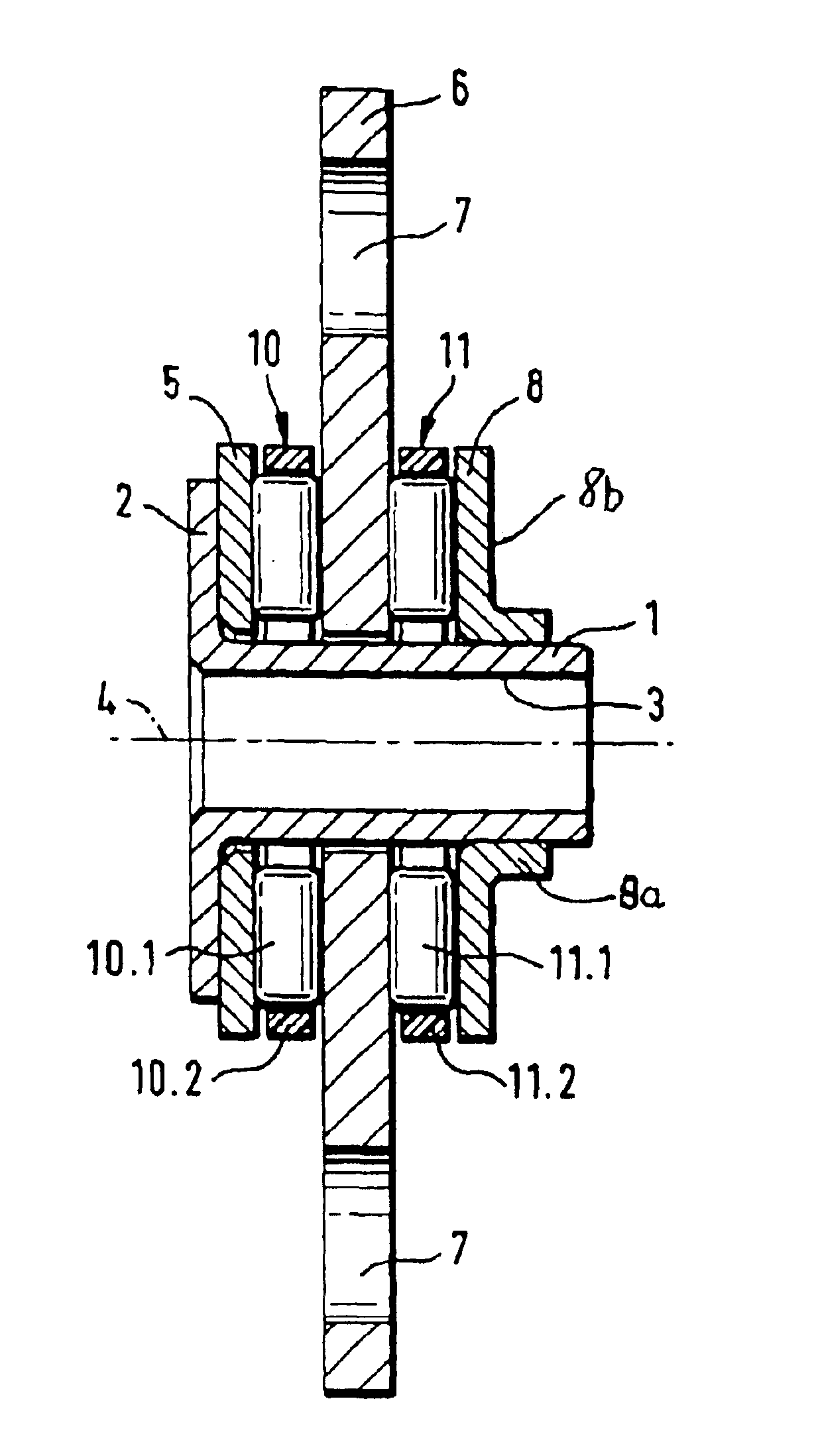
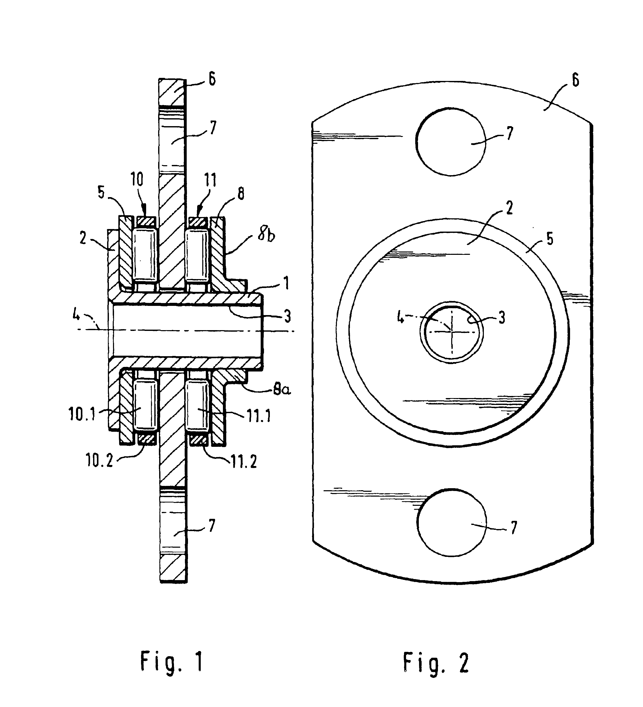
Turning now to the drawing, and in particular to FIG. 1, there is shown a longitudinal section of an axial thrust bearing according to the present invention. The axial thrust bearing is of double-row type and includes a sleeve 1 which has one end (left-hand side in FIG. 1) configured to form a flange 2 which is directed radially outwards. The sleeve 1 is formed with a receiving bore 3 for attachment onto a shaft (not shown) in fixed rotative engagement for rotation about the longitudinal center axis 4. Placed adjacent the flange 2 and thus embraced by the sleeve 1 and the flange 2 is a first outer running disk 5 to provide a raceway for a roller rim, generally designated by reference numeral 10 and including a plurality of bearing needles 10.1 and a cage 10.2 for retaining the bearing needles 10.1. The roller rim 10 is sandwiched between the running disk 5 and a middle running disk 6 which, as also shown by the side view of the thrust bearing in FIG. 2, is provided with fastening bo...

second embodiment

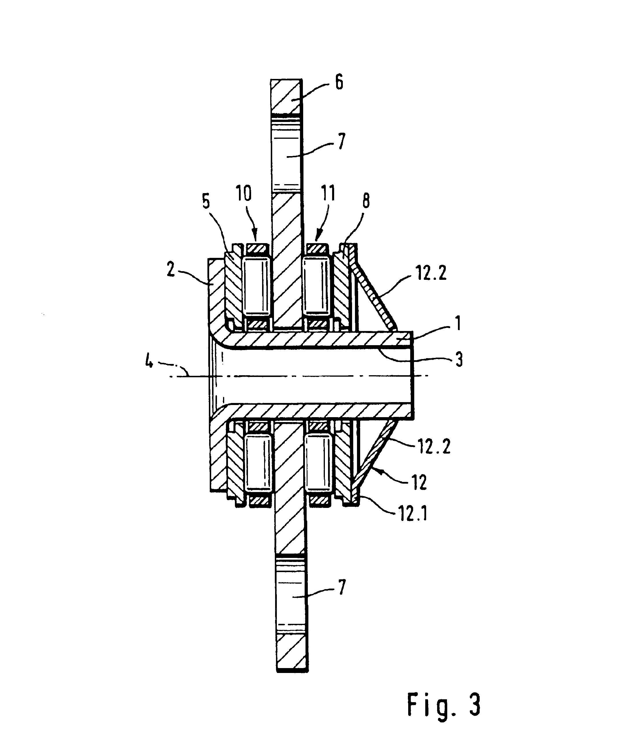
Referring now to FIG. 3, there is shown a longitudinal section of an axial thrust bearing according to the present invention. Parts corresponding with those in FIG. 1 are denoted by identical reference numerals and not explained again. The description below will center on the differences between the embodiments. In the embodiment of FIG. 3, provision is made for a resilient clamping ring, generally designated by reference numeral 12 which is secured to the sleeve 1 and abuts against the outer running disk 8 which has now a flat configuration, instead of an L-shaped configuration.

As shown in particular in FIGS. 4 and 5, the clamping ring 12 has a circular ring shaped base 12.1, which embraces the running disk 8 on the outside, and resilient tabs 12.2, which extend from the base 12.1 radially inwards in spaced-apart relationship. The tabs 12.2 are separated from one another by openings 12.3 and extend at an inclination at an angle toward the longitudinal center axis 4. This ensures th...

third embodiment

FIG. 6 shows a longitudinal section of an axial thrust bearing according to the present invention. Parts corresponding with those in FIG. 3 are denoted by identical reference numerals and not explained again. This embodiment differs from the embodiment of FIG. 3 only by the provision of rolling body rims in the form of ball rims 13, 14. Compared to the roller rims 10, 11, as shown in FIG. 3, the provision of ball rims 13, 13 has the advantage of a reduced friction


PUM


Abstract

An axial bearing includes three running disks disposed in neighboring disposition, thereby defining two outer running disks and a middle running disk between the outer running disks. A first rim of rolling bodies is arranged between one outer running disk and the middle running disk, and a second rim of rolling bodies is arranged between the other outer running disk and the middle running disk. Received in a bore of the first and second rims and supporting the first and second rims of rolling bodies is a sleeve which is securely fixed to a shaft extends in axial direction beyond the outer running disks. The sleeve has one end formed with a radially outwardly directed flange which embraces the adjacent one of the outer running disks, wherein the other outer running disk is securely connected to the sleeve to thereby form a unitary bearing structure.

Description

BACKGROUND OF THE INVENTIONThe present invention relates, in general, to a thrust bearing, and more particularly to a double-row axial thrust bearing of a type having two rims of rolling bodies disposed in side-by-side relationship between a middle and two outer running disks, with both rims supported with their receiving bore on a sleeve securely fixed to a shaft, and with the middle running disk rotatably arranged on the sleeve.A thrust bearing of this type is disclosed in German Offenlegungsschrift DE-OS 20 44 074. The sleeve is securely connected to the shaft and has opposite end surfaces for support of two outer running disks, while the middle running disk, disposed between the outer running disks, encircles the sleeve and is rotatably arranged. The integrity of this thrust bearing is realized by a wedge-shaped split ring which snaps in a wedge-shaped groove on the shaft. This type of thrust bearing has many shortcomings. For one, the wedge-shaped ring and the complementary sha...

Claims


Application Information

Patent Timeline
Patent Type & Authority Patents(United States)
IPC IPC(8): F16C25/00F16C25/08F16C19/02F16C19/10F16C19/22F16C19/30F16C27/08F16C33/58
CPCF16C19/10F16C25/08F16C19/30
Inventor MEIER, PETEROETJEN, JURGEN
Owner INA SCHAEFFLER KG
Why Eureka
Try Eureka