Bottom loading clean room air filter support system

Inactive Publication Date: 2005-02-22
MCGILL
View PDF9 Cites 11 Cited by
  • Summary
  • Abstract
  • Description
  • Claims
  • Application Information

AI Technical Summary

Benefits of technology

The present invention provides clean room filter support systems that may be used in a ceiling or sidewall, and which are less costly, better performing and allow installation of any type of filter. The present invention provides more flexible support systems than any currently available, and includes a plurality of interconnected support elements comprising a grid system for supporting substantially any type of framed filter elements or panels. Additionally, aerodynamic light fixtures and airfoil frame means are preferably added to or formed as lower portions of the

Problems solved by technology

Because the known grid support systems do not always work efficiently, numerous attempts

Method used


Image

  • Bottom loading clean room air filter support system
  • Bottom loading clean room air filter support system
  • Bottom loading clean room air filter support system

Examples


Example

The following description is provided to enable any person skilled in the art to make and use the invention and sets forth the best modes contemplated by the inventor of carrying out his invention. Various modifications, however, will remain readily apparent to those skilled in the art, since the generic principles of the present invention have been defined herein specifically to provide for an improved and simplified bottom loading air filter support system.

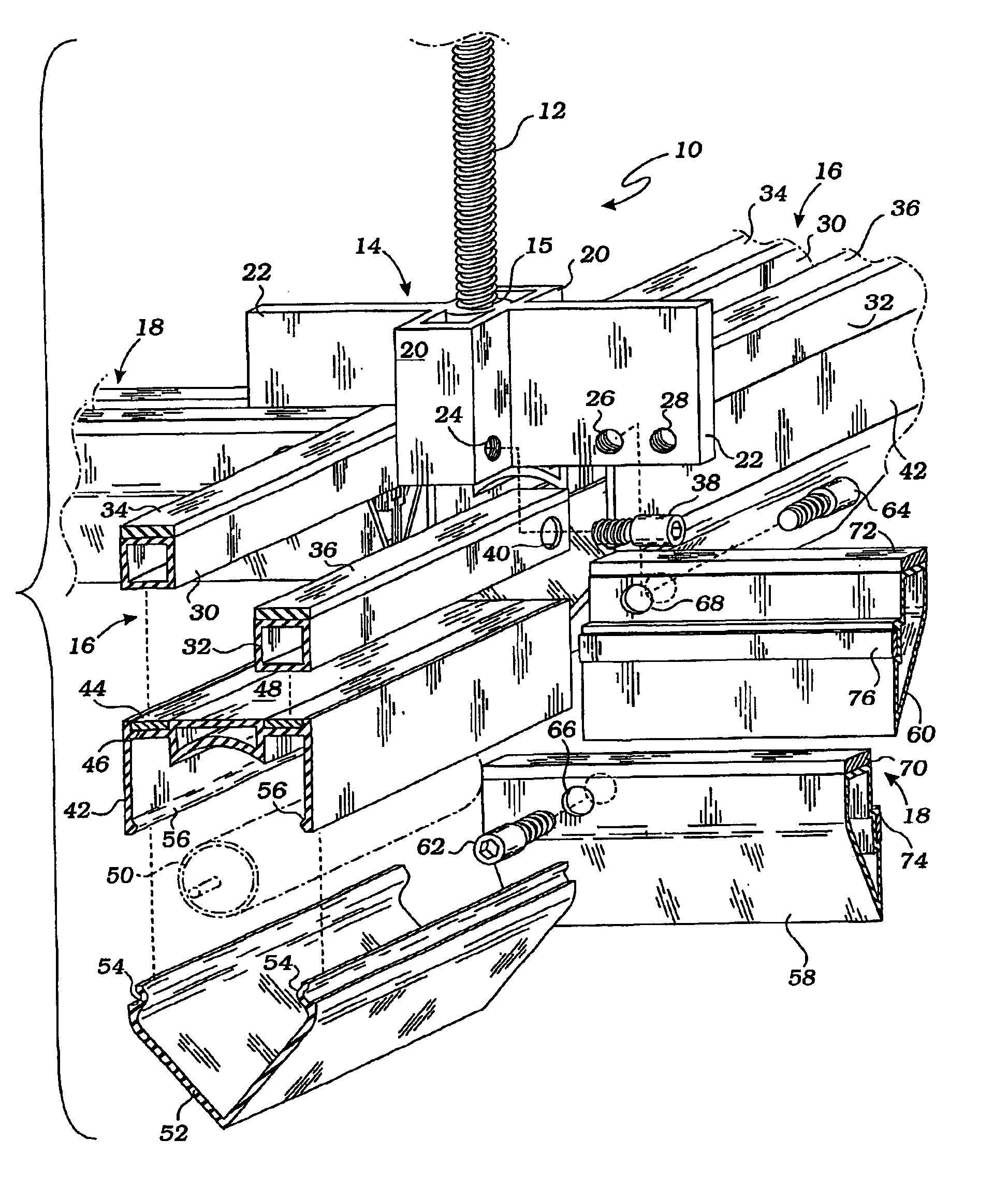
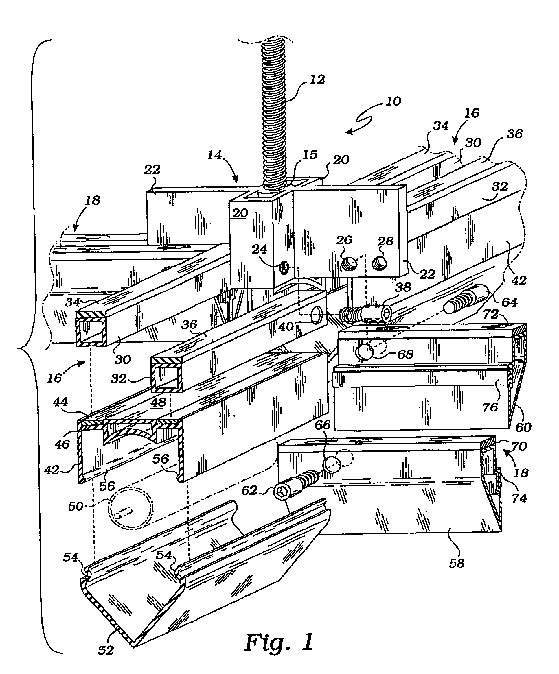
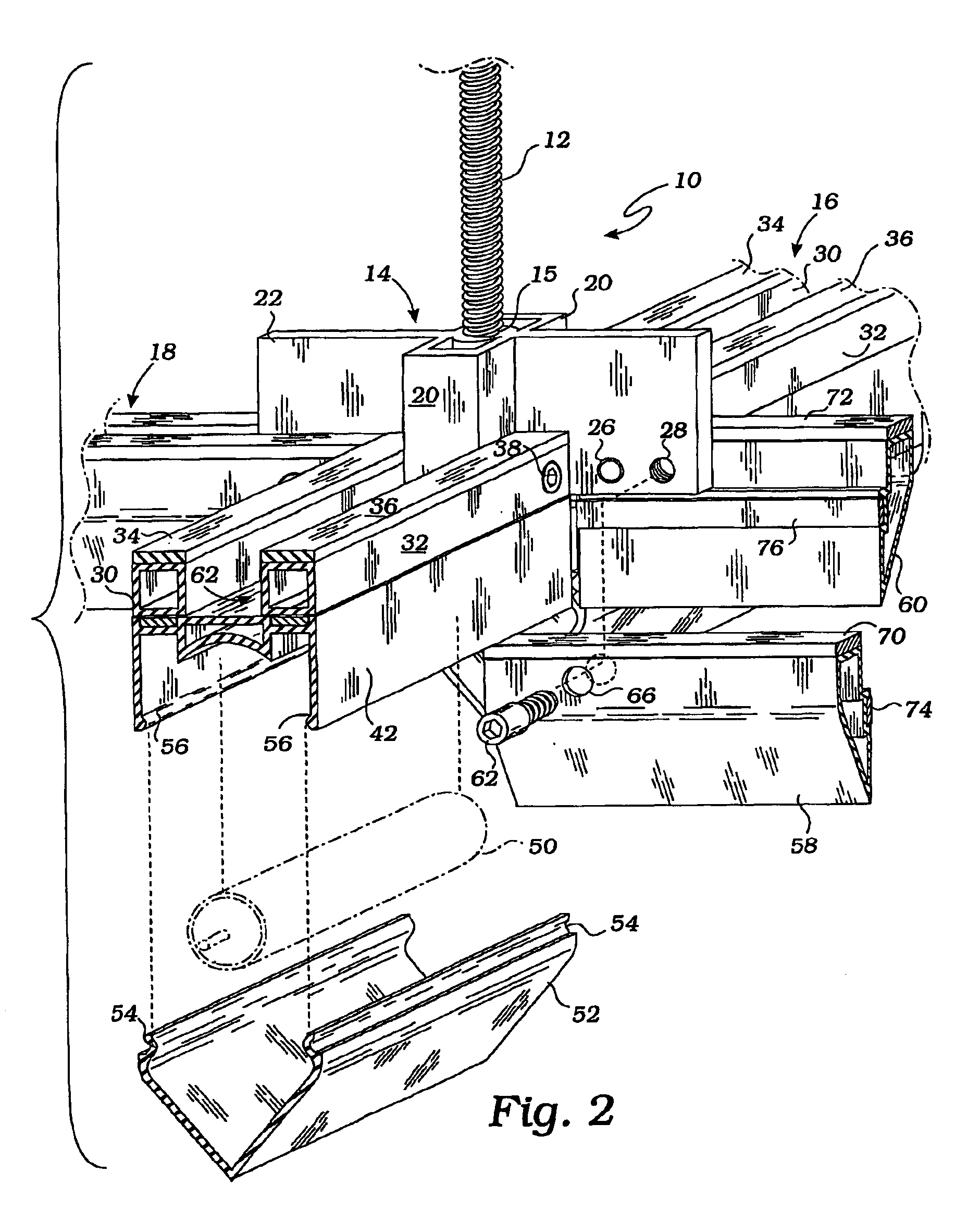
Turning now to the drawings, a preferred embodiment of a bottom loading air filter ceiling support system of the present invention will be described. However, it is to be understood that the air filter support system of the present invention could also be mounted on a sidewall.

The bottom loading air filter support system of the present invention includes a plurality of individual, spaced apart support members 10 having threaded support rods 12, only one of which support members is shown for convenience. Each support rod 12 has a...


PUM

PropertyMeasurementUnit
Angleaaaaaaaaaa
Flow rateaaaaaaaaaa
Sizeaaaaaaaaaa

Abstract

An air filter support system for a clean room has a number of filter support elements (10) supported by holding rods (12) secured to a supporting surface. A connector/hanger bracket (14) having a pair of perpendicular arms (20, 22) with apertures (24, 26,28) formed therein is secured to each holding rod. Grid members (16, 18) are laterally secured to the perpendicular arms by securing elements (38, 62, 64) passing through openings (40, 66, 68). Each of the grid members include sealing gaskets (34, 36, 70, 72) on top surfaces thereof to seal between grid members and filter elements. Aerodynamically shaped light fixtures (42, 52) are secured to lower portions of the grid members (16) to provide non-turbulent air flow into the clean room, while grid members (18) are aerodynamically shaped to provide non-turbulent air flow into the clean room.

Description

FIELD OF THE INVENTIONThis invention relates generally to air filter support systems, and more particularly, to an improved bottom loading supporting system for air filters for clean rooms.DESCRIPTION OF RELATED ARTClean rooms are commonly used in many industries, such as the electronic, medical and pharmaceutical industries, to reduce the number of particles in the air to specified limitations. In the most common approach, a layer of flat filters is suspended from a room ceiling or a sidewall, with the filters extending over the entire area of the ceiling or sidewall. Pressurized air is conducted from a blower through ducts or a plenum through the air filters into an open space in the clean room and then returned via outlets in the room. The filter elements are normally supported by supporting elements, such as a grid, which engages the entire peripheral frame of each filter element. In addition, it is necessary to have an air-sealing gasket or sealing gel positioned between the gr...

Claims


Application Information

Patent Timeline
IPC IPC(8): B01D46/42B01D46/00B01D46/10
CPCB01D46/0005B01D46/10Y10S55/29Y10S55/31B01D2279/51B01D46/00
Inventor MCGILL
Owner MCGILL
Why Eureka
Try Eureka