Method and system for stabilizing thin film transistors in AMOLED displays

a thin film transistor and amoled display technology, applied in the field of video display devices, can solve the problems of unstable tfts and unsuitability for switching elements, and achieve the effect of reducing the effect of threshold dri

Inactive Publication Date: 2005-02-22
EMAGIN CORP
View PDF6 Cites 36 Cited by
  • Summary
  • Abstract
  • Description
  • Claims
  • Application Information

AI Technical Summary

Benefits of technology

The invention also provides a method for controlling a voltage controlled current driving TFT in an active matrix OLED display, which provides updated pixel data to each pixel of the display over a refresh period. The method includes providing a data signal to the current driving ...

Problems solved by technology

A complication associated with employing TFTs to drive OLEDs stems from the fact that TFTs become unstable when operating...

Method used


Image

  • Method and system for stabilizing thin film transistors in AMOLED displays
  • Method and system for stabilizing thin film transistors in AMOLED displays
  • Method and system for stabilizing thin film transistors in AMOLED displays

Examples


Embodiment Construction

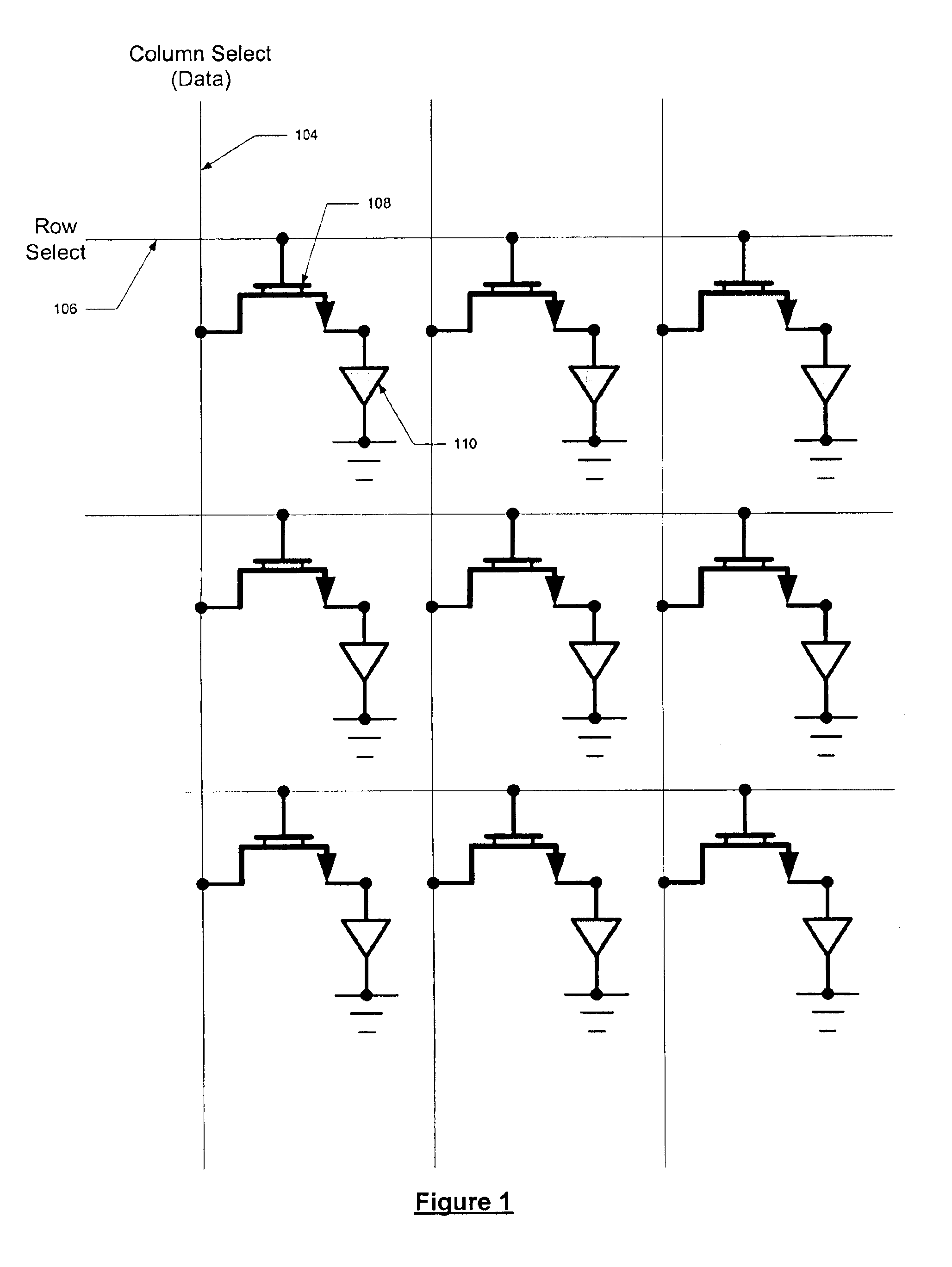
FIG. 1 illustrates an arrangement of TFT switching elements and OLED display elements, which follows conventional active matrix display architecture. In the conventional method, each display element 110 is associated with a corresponding TFT 108. In an AMLCD display, the display element is a liquid crystal cell. In FIG. 1, the display element is illustrated as a diode so as to provide an example operation of the display when driving OLEDs in the conventional manner. As may be appreciated, in FIG. 1, each OLED corresponds to a pixel of the display. In other embodiments, a group of OLEDs forms one pixel element, whereby each OLED provides a different color to the pixel element. The gate of the TFT 108 is coupled to a row select line 106. The source of the TFT 108 is coupled to a column data line 104, which provides data signals to the TFT 108.

In operation, the row select line 106 provides a signal to switch on each TFT 108 once during each refresh period of the display. Accordingly, e...


PUM


Abstract

An active matrix OLED display includes current driving TFT transistors to provide current to corresponding OLEDs. The control signals to each TFT gate include a data signal that is proportional to the desired luminance output for the OLED and a reverse data signal that is used to reverse bias the TFT to prevent threshold drift in the TFT. The data signal alteration is preformed either at a frame rate or at a line rate.

Description

FIELD OF THE INVENTIONThe present invention is related to video display devices, and particularly to Active Matrix Organic Light Emitting Diode (AMOLED) display devices.BACKGROUNDRecent advances in technology have made active matrix technology more attractive to employ in Organic Light Emitting Diode (OLED) video displays. Specifically, Thin Film Transistor (TFT) based active matrix displays provide the size and manufacturing cost efficiencies that are attractive to OLED video displays. In the conventional active matrix display, such as those employing Liquid Crystal Display elements (AMLCD), TFTs are used as driving elements to vary the orientation of the liquid crystals and thereby switch corresponding pixels off and on. In the case of OLEDs, active matrix technology allows efficient DC operation of each pixel, rather than row-by-row high frequency pulsed operation, as is required in passive matrix displays. For this reason, active matrix technology is expected to be widely used i...

Claims


Application Information

Patent Timeline
IPC IPC(8): G09G3/32
CPCG09G3/3233G09G3/3241G09G2320/043G09G2310/0251G09G2310/0254G09G2300/0842
Inventor HOWARD, WEBSTER E.
Owner EMAGIN CORP
Why Eureka
Try Eureka