Collision damage reduction system

a collision damage and reduction system technology, applied in the field of vehicle collision avoidance systems, can solve the problems of difficult identification of the first vehicle, the possibility of collision between the vehicles and/or the actual collision therebetween, and many of the above discussed limitations, so as to improve the effect of avoiding collisions and reduce the damage in collisions

Inactive Publication Date: 2005-02-22
DENSO CORP
View PDF12 Cites 60 Cited by
  • Summary
  • Abstract
  • Description
  • Claims
  • Application Information

AI Technical Summary

Benefits of technology

In view of the foregoing, it is an object of the present invention to provide a collision damage reduction system that is capable of improving effects of avoiding a collision and / or reducing damage in a collision.

Problems solved by technology

The sudden variation in the shape of the time-space region causes the problem such that the possibility of collision between the vehicles and / or the actual collision therebetween occurs even if the collision avoidance technique judges that no collision occurs according to the collision probability.
In addition, the first vehicle must regularly communicate with vehicles in proximity thereto so that, in cases where the first vehicle runs on a congested road, it is difficult for the first vehicle to identify data sent from the other vehicles as data corresponding to the vehicle closest to the first vehicle.
Furthermore, use of the above collision probability operation technique of the Japanese Patent Publication for a protecting device that effectively protects occupants in a vehicle at the time of actual collision is not disclosed.
However, the above conventional techniques, still include many of the above discussed limitations except for the limitation related to inter-vehicle communication.

Method used


Image

  • Collision damage reduction system
  • Collision damage reduction system
  • Collision damage reduction system

Examples


first modification

(First Modification)

In this embodiment, no control of the steering angle of the vehicle 100 is performed. However, in the first modification, control of the steering angle of the own vehicle may be performed. More specifically, the microcomputer 3 may force, on the basis of a probability distribution including each collision probability Pr1 (θr1) of each steering angle θ(r1), the vehicle 100 to be guided (steered) in a direction to which the value of the collision probability Pr1 (θr1) is decreased, or may brake the vehicle 100.

second modification

(Second Modification)

In this embodiment, using the total collision probability Pr based on each of the performance limit data of each of the vehicle and the object allows the operation of at least one of the collision avoidance units and the collision damage reduction units to be controlled. However, in the second modification, it may be possible to control at least one of the collision avoidance units and the collision damage reduction units according to a distribution of the collision probabilities (local collision probabilities) in the X direction based on the each of the performance limit data of each of the vehicle and the object. For example, it may be possible to force the vehicle to be guided (steered) in a direction to which the value of the collision probability in the X direction is decreased, or a direction to which the absolute value of the relative speed is decreased.

third modification

(Third Modification)

In this embodiment, the speed of each of the vehicle and the object is assumed to be kept at each of the current speeds of each of the vehicle and the object after each of the current speeds are detected. However, the current speed rate may be kept. Moreover, in the vehicle, any speed may be set within the range of the maximum decelerating rate determined by the performance limit data of the vehicle, and similarly, in the object, any speed may be set within the range of the maximum decelerating rate determined by the performance limit data of the object.

In addition, the current speed rate may be assumed to be kept until the speed of the vehicle suddenly changes. After the suddenly change of the speed, the current speed of the vehicle may be assumed to be decelerated at the maximum decelerating rate of the vehicle as determined by the performance limit data thereof. Similarly, the current speed rate may be assumed to be kept until the speed of the object suddenly ...


PUM


Abstract

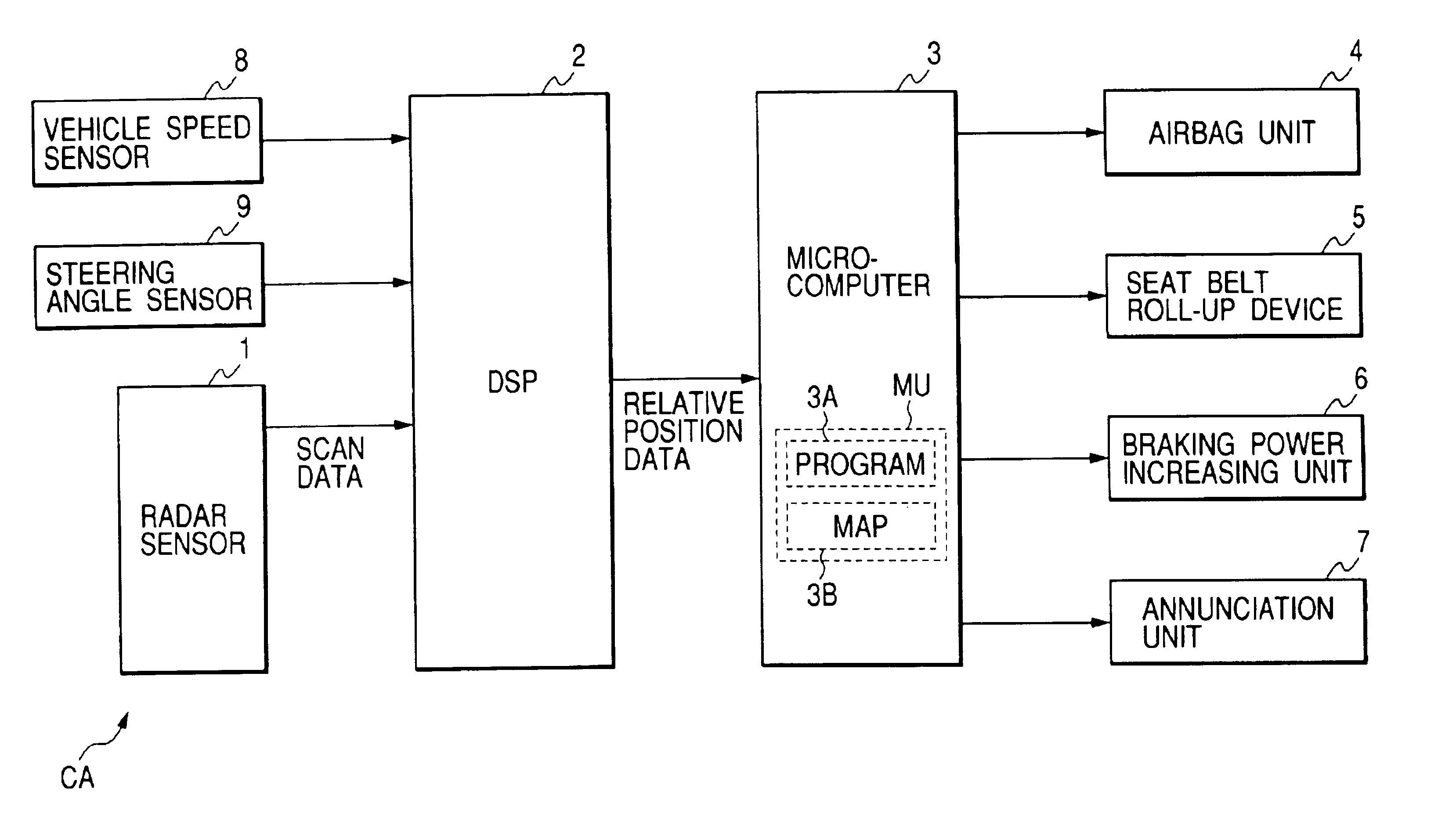
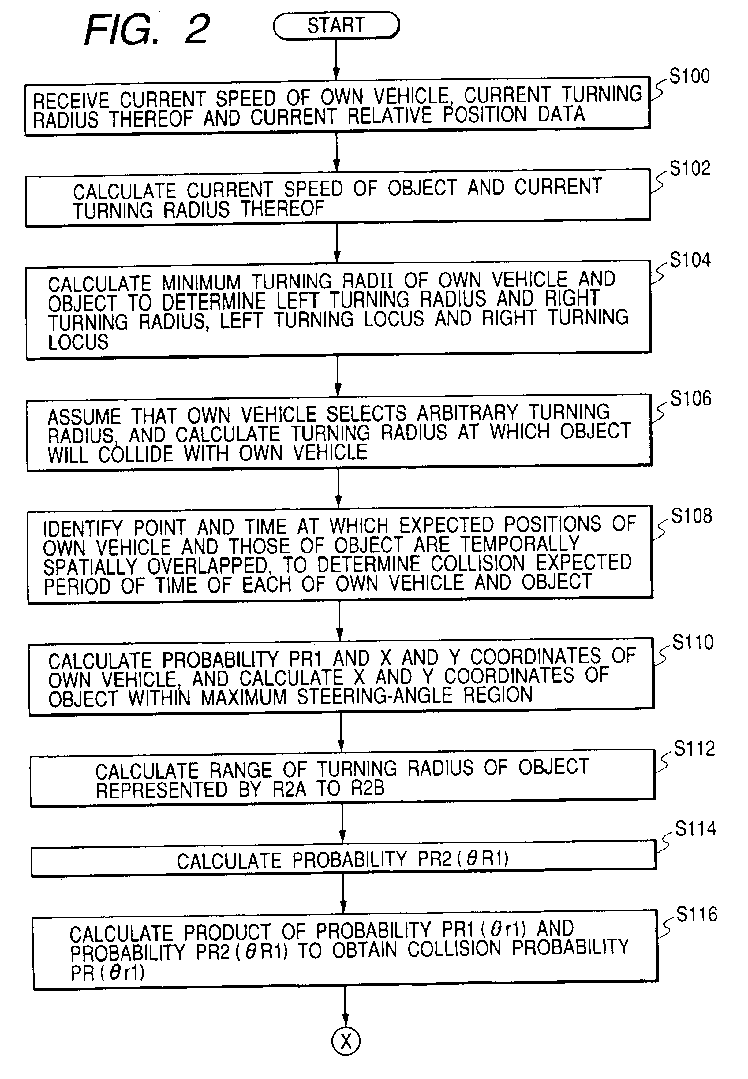
In a collision damage reduction system, a microcomputer obtains relative position data corresponding to a relative between a vehicle and an object from a first detecting unit, the detected speed of the vehicle as detected by a second detecting unit, the detected turning angle of the vehicle as detected by a third detecting unit. The microcomputer calculates a total collision probability representing a probability that the vehicle and the object will collide on a runnable space according to the relative position data, the detected speed of the own vehicle and the detected turning angle. In addition, the microcomputer instructs the operation unit to operate at least one of a first collision avoidance operation and a second collision avoidance operation according to the total collision probability.

Description

BACKGROUND OF THE INVENTIONCROSS REFERENCE TO RELATED APPLICATIONThis application is based upon and claims the benefit of priority of Japanese Patent Application 2002-7103 filed on Jan. 16, 2002, the contents of which are incorporated herein by reference.1. Field of the InventionThe invention relates vehicle collision avoidance systems, and particularly to a collision damage reduction system for reducing damage in a collision.2. Description of the Related ArtJapanese Patent Publication No. 2000-276696 discloses a collision probability operation technique that generates probability distribution information representing a probability distribution that a first vehicle will be present in time and space substantially in the running direction thereof, and that transmits the probability distribution information to a second vehicle in the vicinity of the first vehicle.In addition, the collision probability operation technique receives probability distribution information representing a prob...

Claims


Application Information

Patent Timeline
Patent Type & Authority Patents(United States)
IPC IPC(8): B60R21/01G08G1/16B60K28/14B60R21/00B60R21/013B60R21/0134B60R21/16B60R22/46B60R22/48B60T7/12B60W10/18B60W30/08B60W50/08B60W50/14
CPCB60R21/0132G08G1/16B60W10/18B60W10/20B60W30/08B60R21/0134B60R2021/01259B60R2021/01265B60R2021/01313B60W2050/143B60W2510/20B60W2520/10B60W2550/20B60W2550/308B60W2550/402G08G1/166G08G1/164B60W2554/00B60W2554/801B60W2556/50B60W2540/18G01P15/00B60W2554/80
Inventor TAKAFUJI, TETSUYASUZUKI, TOMOJI
Owner DENSO CORP
Why Eureka
Try Eureka