
Windshield wiper assembly having a winter boot

a technology of windshield wiper and boot, which is applied in the field of winter boot, can solve the problems of reducing the wiping effectiveness unable to provide contact between the windshield and all parts of the wiper blade, and unable to meet the needs of cleaning,

Inactive Publication Date: 2005-03-01
JAMAK FABTION TEX
View PDF20 Cites 37 Cited by
  • Summary
  • Abstract
  • Description
  • Claims
  • Application Information

AI Technical Summary

Benefits of technology

The problems presented by natural rubber and EPDM winter boots are solved by the present invention. A protective wiper boot is provided that includes a flexible cover made of a silicone elastomer compound. Preferably, the flexible cover conforms to the shape of a wip

Problems solved by technology

A critical problem encountered by windshield wiper designers has been how to maintain contact between a wiper blade and a windshield at all times throughout the windshield wiping process.
Different automobiles typically have windshields of different sizes and shapes, and providing contact between the windshield and all parts of a wiper blade can be a difficult task.
A bare windshield wiper is rendered largely ineffective during winter weather when snow, sleet, or ice accumulate on the flexural members of wiper frames.
Since the wiper blade does not fully contact the windshield, the wiping effectiveness of the wiper blade is significantly decreased.
The natural rubber and EPDM used in wiper blades, however, perform poorly when subjected to low temperatures such as those encountered in freezing climates.
), the material reaches a glass transition temperature and begins to lose flexibility.
Since the winter boot surrounds the wiper frame, the decreased flexibility of the winter boot hinders the proper movement of the flexural members and joints of the wiper frame.
The overall result is poor contact between the wiper blade and the windshield, which reduces the wiping ability of the wiper blade.
Additionally, EPDM and natural rubber deteriorate rapidly when exposed to ultra-violet radiation and ozone.

Method used


Image

  • Windshield wiper assembly having a winter boot
  • Windshield wiper assembly having a winter boot
  • Windshield wiper assembly having a winter boot

Examples


Embodiment Construction

In the following detailed description of the preferred embodiments, reference is made to the accompanying drawings which form a part hereof, and in which is shown by way of illustration specific preferred embodiments in which the invention may be practiced. These embodiments are described in sufficient detail to enable those skilled in the art to practice the invention, and it is understood that other embodiments may be utilized and that logical mechanical and chemical changes may be made without departing from the spirit or scope of the invention. To avoid detail not necessary to enable those skilled in the art to practice the invention, the description may omit certain information known to those skilled in the art. The following detailed description is, therefore, not to be taken in a limiting sense, and the scope of the present invention is defined only by the appended claims.

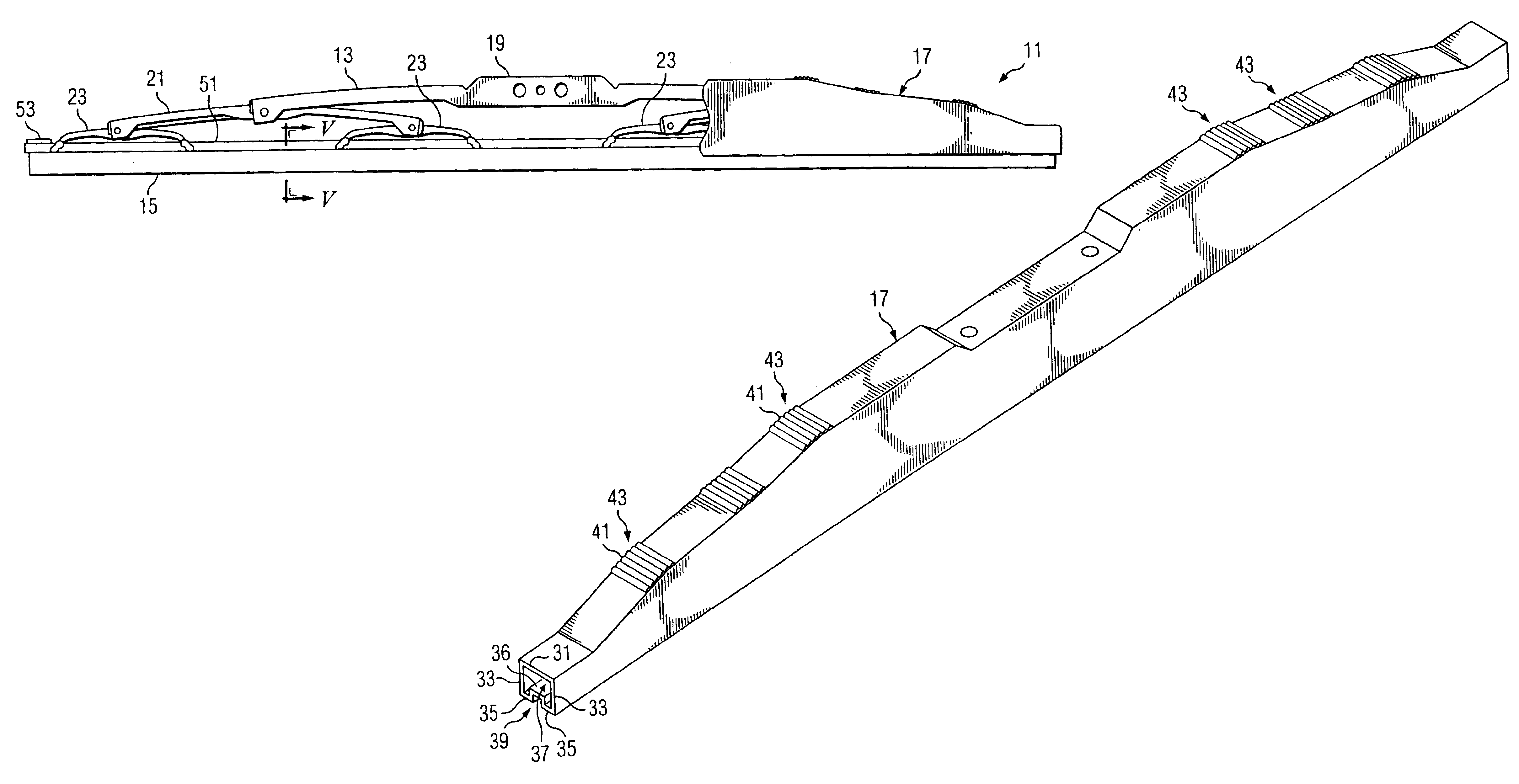
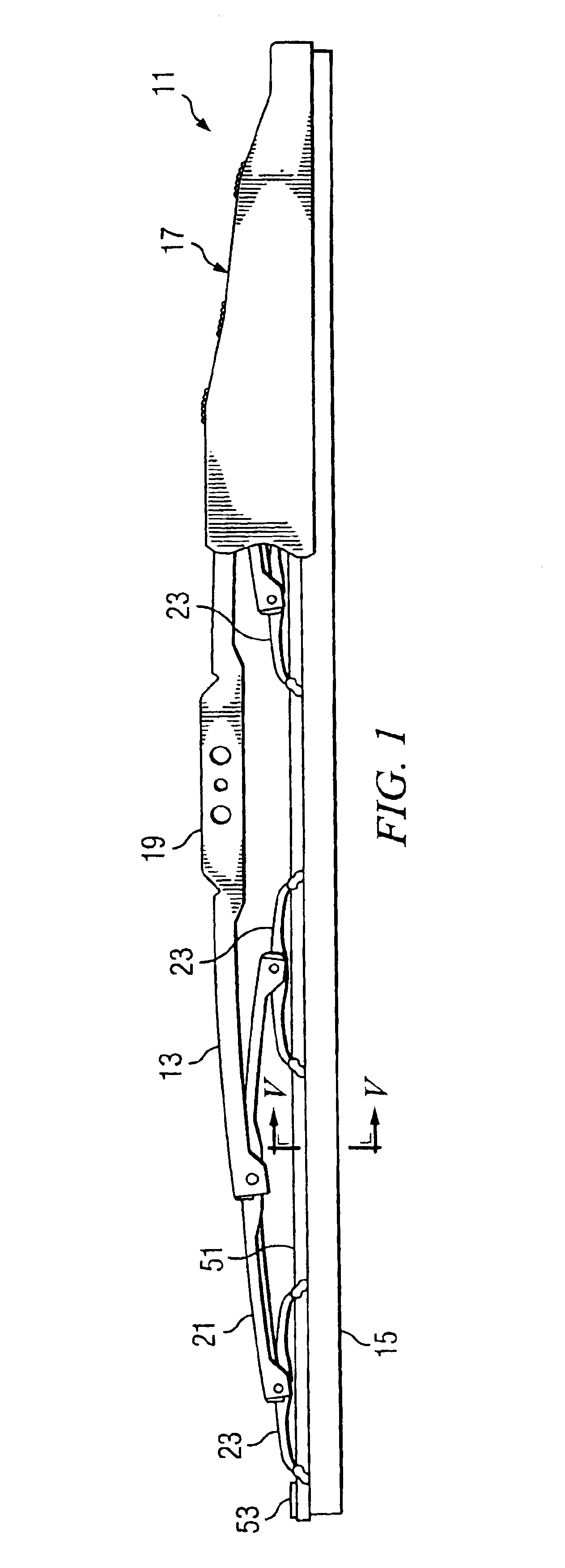
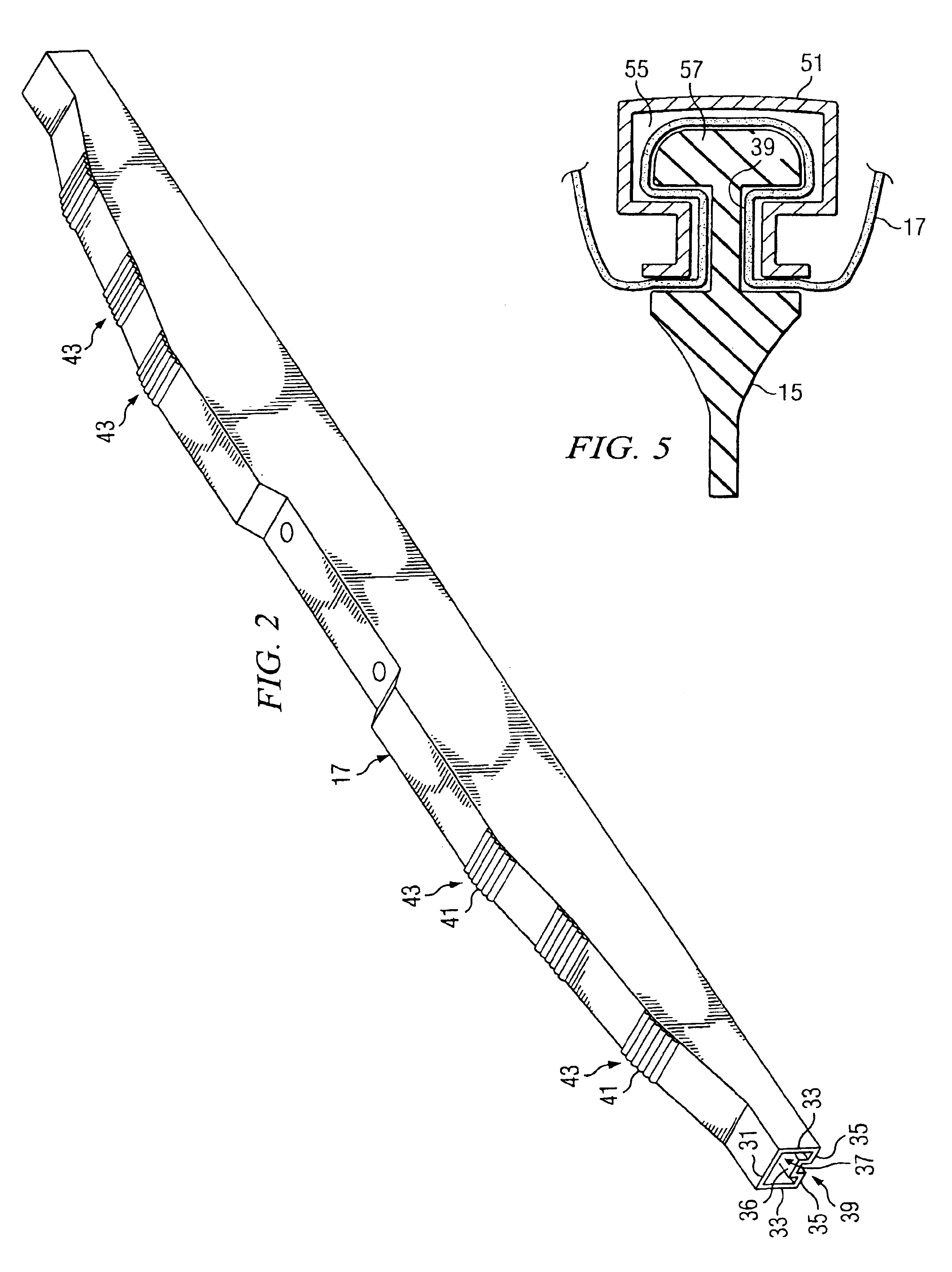
Referring to FIG. 1 in the drawings, a wiper assembly 11 having a wiper frame 13, a wiper blade 15, and a...


PUM


Abstract

A wiper assembly having a wiper frame and a wiper boot is provided. The wiper boot includes an upper wall integrally connected between two side walls. A lower leg is integrally connected to each side wall at an end opposite that of the upper wall. Each lower leg runs transversely and inwardly from the side walls, the lower legs integrally connecting to a u-shaped wall. The upper wall, the side walls, the lower legs, and the u-shaped wall define a cavity that receives the wiper frame. The wiper boot is made from silicone elastomer that preferably includes approximately 30 to 60 weight percent of polyvinylmethylsiloxane, approximately 15 to 40 weight percent of filler, approximately 0.1 to 10 weight percent of pigment, and approximately 0.1 to 10 weight percent of catalyst.

Description

BACKGROUND OF THE INVENTION1. Field of the InventionThis invention relates generally to windshield wiper assemblies, and more particularly to a winter boot for protecting a windshield wiper assembly from harsh environmental conditions.2. Description of Related ArtA critical problem encountered by windshield wiper designers has been how to maintain contact between a wiper blade and a windshield at all times throughout the windshield wiping process. One complicating factor is that a particular wiper blade may be designed to fit on many different automobile models. Different automobiles typically have windshields of different sizes and shapes, and providing contact between the windshield and all parts of a wiper blade can be a difficult task. One design solution to the problem has been to provide wiper frames having spring-like flexural members attached to the frames. The flexural members exert forces at various points along the wiper blade to insure contact of the blade with the winds...

Claims


Application Information

Patent Timeline
IPC IPC(8): B60S1/38
CPCB60S1/3801B60S2001/3843
Inventor SIKLOSI, TIBOR
Owner JAMAK FABTION TEX
Learn More