
Pedal feel emulator mechanism for brake by wire pedal

a pedal feel and emulator technology, applied in the direction of mechanical control devices, braking systems, instruments, etc., can solve problems such as hysteresis effects

Inactive Publication Date: 2005-04-21
DURA GLOBAL TECH
View PDF4 Cites 46 Cited by
  • Summary
  • Abstract
  • Description
  • Claims
  • Application Information

AI Technical Summary

Benefits of technology

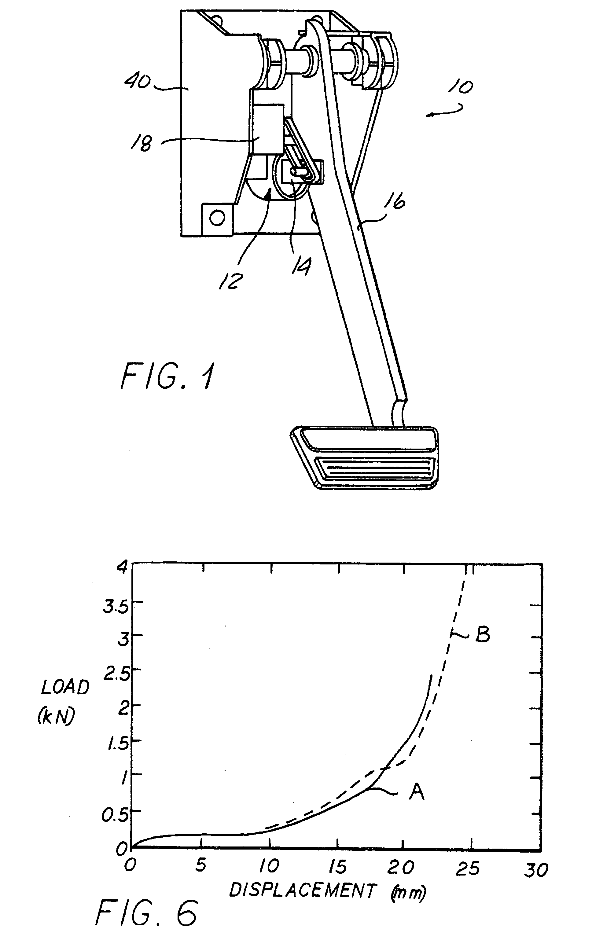
[0011] The above object as well as other objects which will become apparent upon a reading of the following specification and claims is achieved by a simple, reliable emulator mechanism which causes the brake pedal motion to compress a resiliently compressible foamed plastic elastomeric piece in such a way as to achieve the complex relationship between pedal motion and sensed resistance and also to provide the necessary hysteresis effect which is produced by the pedal for operating a conventional hydraulic brake system. The foamed plastic elastomeric piece provides an increased rate of increase in reaction force after the voids therein are substantially collapsed, and also can be easily formulated to provide hysteresis.
[0013] In another approach, a foamed plastic elastomeric piece having sufficient inherent hysteresis is combined with a mechanical spring to eliminate the need for a separate hysteresis device while being more easily matched to a force-travel function of a conventional hydraulic brake system pedal.

Problems solved by technology

This frictional resistance creates hysteresis in that the friction that must be overcome to move the pedal is substantially more than the force required to merely hold the pedal in a depressed position, simulating the feel of a mechanical accelerator pedal.
Thus, there is a complex relationship between the pedal motion and sensed pedal reaction force and there also is a hysteresis effect in that the apply force is less than the return force due to the loss of energy in a hydraulic system.

Method used


Image

  • Pedal feel emulator mechanism for brake by wire pedal
  • Pedal feel emulator mechanism for brake by wire pedal
  • Pedal feel emulator mechanism for brake by wire pedal

Examples


Embodiment Construction

[0035] In the following detailed description, certain specific terminology will be employed for the sake of clarity and a particular embodiment described in accordance with the requirements of 35 USC 112, but it is to be understood that the same is not intended to be limiting and should not be so construed inasmuch as the invention is capable of taking many forms and variations within the scope of the appended claims.

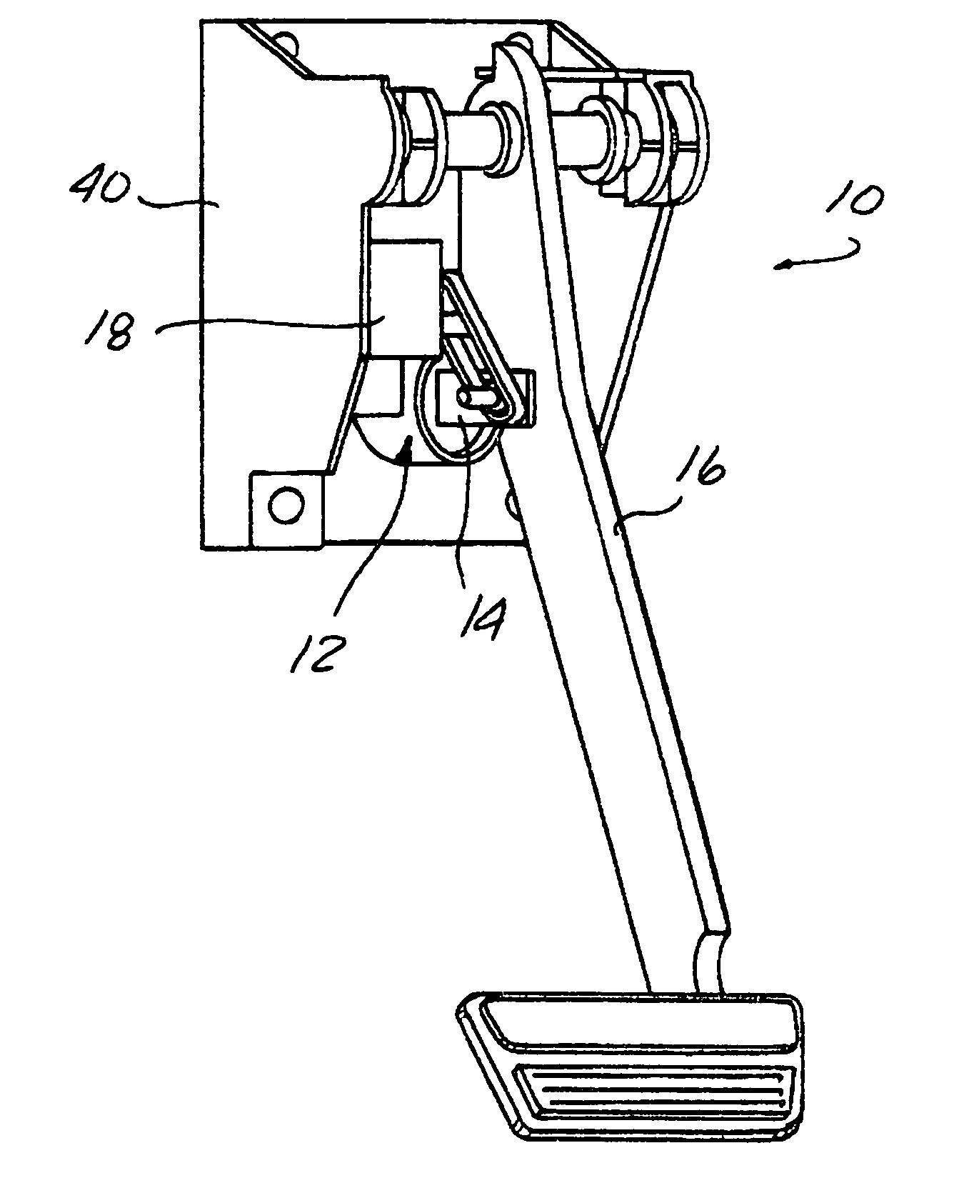
[0036]FIG. 1 shows a view of a brake pedal assembly 10 which includes a brake pedal feel emulator device 12 for use with an electronic brake by wire system. A plunger clevis 14 is pinned to the brake pedal 16 and operates the brake pedal emulator mechanism 12. The brake pedal 16 also drives a position sensor 18 to generate a signal used by the brake by wire system (not shown) in the well known fashion.

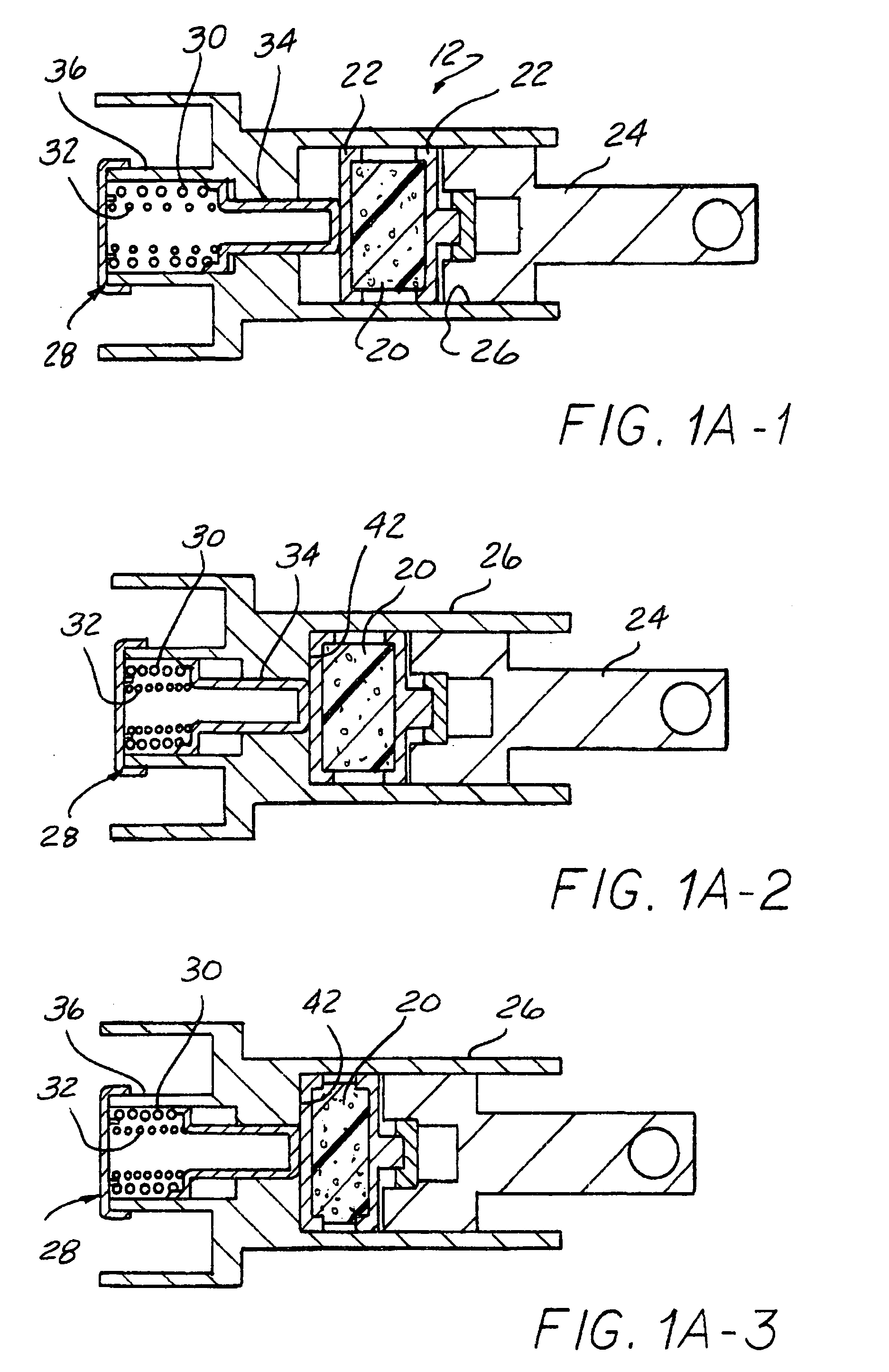
[0037] Referring to FIG. 1A-1, the emulator mechanism 12 includes a foamed plastic elastomeric piece 20 confined between two plates 22 in a chamber 26 to be compressed b...


PUM


Abstract

A brake pedal emulator mechanism includes a foamed plastic elastomeric piece compressed by a brake pedal which piece has a variable spring rate and produces hysteresis when compressed to emulate the brake pedal feel of a conventional hydraulic brake system. The foamed plastic may comprise microcellular urethane or a foamed silicone elastomer. Various combinations of the foamed plastic piece with mechanical springs, solid elastomeric pieces, or gas springs can be used to create a particular reaction force characteristic, as well as various shapes of the foamed plastic elastomeric piece itself.

Description

CROSS REFERENCE TO RELATED APPLICATIONS [0001] This application claims the benefit of U.S. provisional application Ser. No. 60 / 512,844, filed on Oct. 20, 2003.BACKGROUND OF THE INVENTION [0002] This invention concerns devices for replicating the pedal “feel” of a conventional hydraulic brake in an electronically operated brake systems, often referred to as “brake by wire” systems. Such brake by wire systems have been proposed in which displacement and force sensors are associated with the pedal which generate signals used to control the operation of the wheel brakes. In operating a brake by wire system, a driver typically feels more comfortable when the pedal feel is similar to the pedal feel of a conventional brake system, and thus designers have sought to achieve this. [0003] In addition, it is desirable that the sensed foot pressure corresponds to a similar braking effect in both conventional and brake by wire brake systems. [0004] A major characteristic of conventional hydraulic...

Claims


Application Information

Patent Timeline
IPC IPC(8): B60T7/04B60T8/32B60T8/40B60T17/02G05G1/38G05G1/44G05G5/03
CPCB60T7/042B60T8/3255G05G5/03G05G1/38G05G1/44B60T17/02
Inventor CONSTANTAKIS, CRISTA M.SUNDARESAN, SRINIKICZEK, CASIMIR R.
Owner DURA GLOBAL TECH
Learn More