Chassis dynamometer

a dynamometer and chassis technology, applied in the direction of force measurement, force measurement, instruments, etc., can solve the problems of adding undesirable complexity and additional cost to the machine, and not being able to regenerate the absorbed power,

Inactive Publication Date: 2005-03-01
POWER TEST LLC
View PDF22 Cites 23 Cited by
  • Summary
  • Abstract
  • Description
  • Claims
  • Application Information

AI Technical Summary

Problems solved by technology

However, with the advent of higher horsepower vehicles, it has become necessary to have machines that require greatly oversized motors or electric dynamometers to provide full vehicle power absorption while still providing the lesser power required for driving the rollers.
An additional disadvantage of using a large motor or electric dynamometer is the necessity to dissipate heat generated through a resistive load bank or to regenerate the absorbed power as electrical power.
Both these functionalities add undesirable complexity and additional cost to the machine.

Method used


Image

  • Chassis dynamometer
  • Chassis dynamometer
  • Chassis dynamometer

Examples


Embodiment Construction

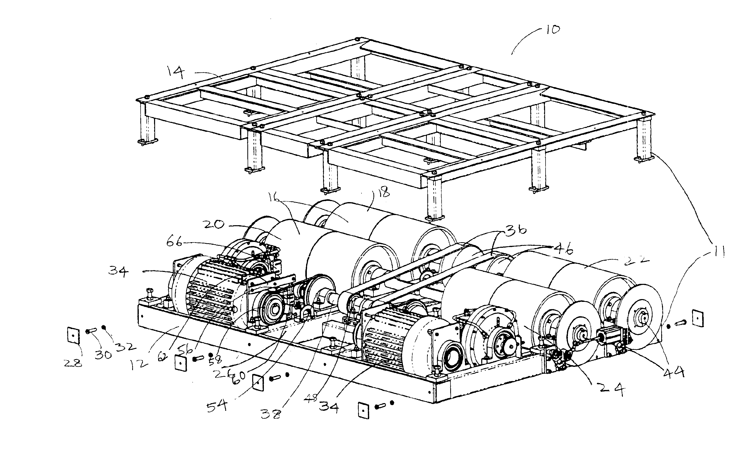
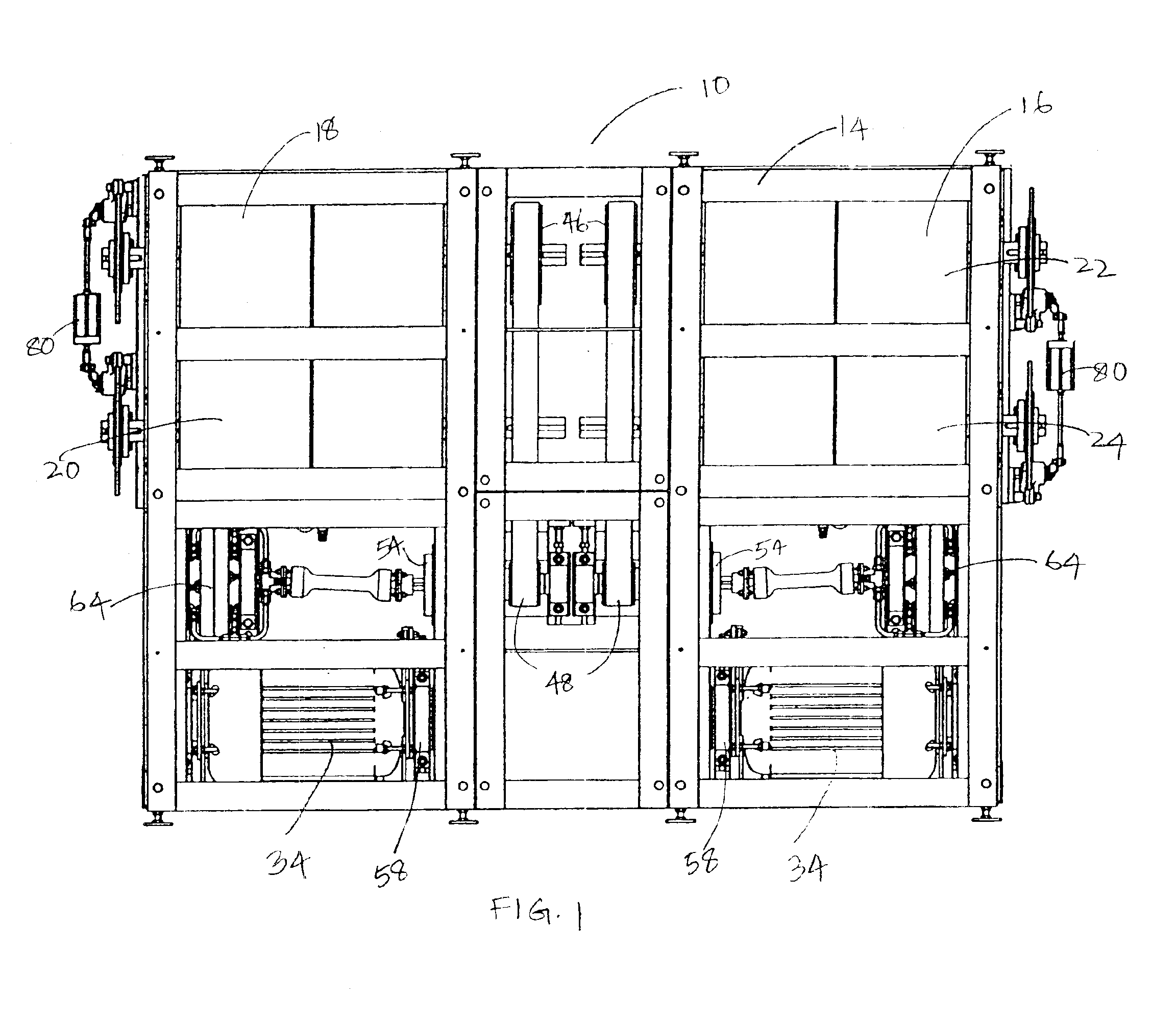
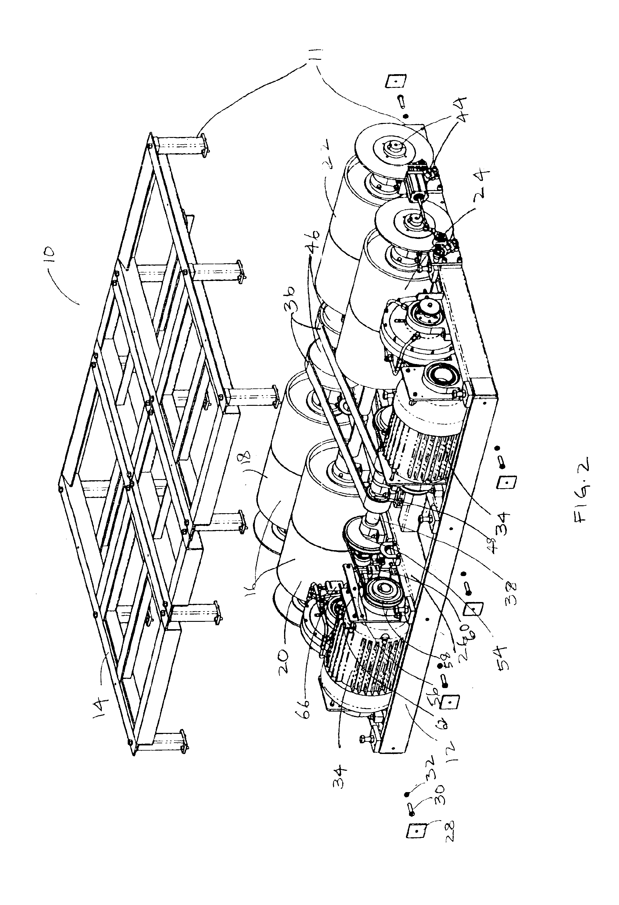
Referring now to the drawings and in particular FIGS. 1, 2, 3 and 4, one preferred embodiment of a motorized chassis dynamometer machine 10 generally comprises a fixed frame assembly 11 and a movable frame assembly (not shown). Since the fixed frame assembly 11 and the movable frame assembly are identical in operation to each other except for the mobility of the movable frame assembly, only the operational features and functionality of the fixed frame assembly 11 will be discussed in detail. Methods for operating a movable frame relative to a fixed frame assembly are known to one of ordinary skill in the art.

The fixed frame assembly 11 generally includes a lower structure assembly 12 and an upper structure assembly 14. The upper structure 14 and the lower structure 12 are removably held together by traditional means known to one of ordinary skill in the art. In one preferred embodiment, the upper and lower structures 14, 12 are removably held together by nuts and bolts. The upper an...


PUM

PropertyMeasurementUnit
torqueaaaaaaaaaa
speedaaaaaaaaaa
resistanceaaaaaaaaaa

Abstract

A motorized chassis dynamometer machine. In one embodiment, the dynamometer machine includes a fixed frame assembly. At least one roller assembly is mounted on the fixed frame assembly. At least one independent motor assembly is connected to each roller assembly. The independent motor assembly is used for driving the roller assembly. At least one independent loading dynamometer assembly capable of measuring the vehicle input power at each roller assembly is coupled to each roller assembly. In a preferred embodiment, the dynamometer assembly is only operable for loading each independent roller assembly, while the motor assembly is operable for driving each independent roller assembly. The machine has at least one motor controller capable of controlling each independent motor assembly and at least one dynamometer controller capable of controlling each independent dynamometer assembly. Each roller assembly, motor controller and dynamometer controller are in turn controlled and manipulated by an overall controller. The dynamometer machine may further include a torque sensor for each motor assembly and each dynamometer assembly. The torque sensors are used to measure torque reaction, each torque sensor independently measuring torque for each of the roller assemblies.

Description

BACKGROUND OF THE INVENTIONThis invention generally relates to dynamometers and specifically to a chassis dynamometer for transit vehicles.The art of making various dynamometers has existed for decades. Continuous improvement in the construction of dynamometers for activities including brake testing, performance testing and emissions testing is evidenced by a series of issued patents including U.S. Pat. No. 5,375,461 to Suzuki, U.S. Pat. No. 4,450,728 to D'Angelo et. al., U.S. Pat. No. 4,468,955 to Yamasaki et. al., U.S. Pat. No. 4,688,419 to D'Angelo et al., U.S. Pat. No. 4,870,585 to Manzolini, U.S. Pat. No. 5,010,763 to Schneider, U.S. Pat. No. 3,277,703 to Cline, U.S. Pat. No. 3,554,023 to Geul, U.S. Pat. No. 6,257,054 to Rostkowski et. al., U.S. Pat. No. 5,193,386 to Hesse, Jr. et. al., U.S. Pat. No. 5,844,145 to D'Angelo, U.S. Pat. No. 5,450,748 to Evans et al., U.S. Pat. No. 4,483,204 to Warsaw, U.S. Pat. No. 4,899,595 to Warsaw, U.S. Pat. No. 3,289,471 to Maxwell, U.S. Pat. ...

Claims


Application Information

Patent Timeline
Patent Type & Authority Patents(United States)
IPC IPC(8): G01L5/28
CPCG01L5/282
Inventor BERGST, ALLEN BCHILDERS, JOHN RPETELINSEK, JOHN FPETELINSEK, ALAN DSTRAIN, DANIEL DJOHNSON, GREGORY
Owner POWER TEST LLC
Why Eureka
Try Eureka