
Circular saw having saw arm angle adjusting device

a technology of angle adjustment and circular saw, which is applied in the direction of metal sawing devices, metal sawing apparatus, manufacturing tools, etc., can solve the problems of inability to micro-adjust the angle of the saw arm relative to the base, the angle adjustment device only provides a larger angle adjustment function, and the disadvantage of users, etc., to achieve the effect of reducing the disadvantage and/or avoiding the disadvantag

Inactive Publication Date: 2005-03-01
REXON
View PDF4 Cites 17 Cited by
  • Summary
  • Abstract
  • Description
  • Claims
  • Application Information

AI Technical Summary

Benefits of technology

The present invention is to mitigate and / or obviate the disadvantage of the conventional angle adjusting device of the circular saw.
The primary objective of the present invention is to provide a circular saw having a saw arm angle adjusting device that can facilitate the user's operation.
Another objective of the present invention is to provide a circular saw having a saw arm angle adjusting device, wherein the inclined angle of the saw arm can be adjusted and positioned easily and conveniently before operation of the circular saw, thereby facilitating the user operating the circular saw.
A further objective of the present invention is to provide a circular saw having a saw arm angle adjusting device, wherein the mounting tube is combined with the positioning bolt, thereby saving time of assembly.
A further objective of the present invention is to provide a circular saw having a saw arm angle adjusting device, wherein the first end of the positioning bolt is combined with the second end of the mounting tube and the locking nut is screwed on the second end of the positioning bolt for positioning the positioning bolt, thereby preventing detachment of the positioning bolt due to excessive rotation.

Problems solved by technology

The adjusting device is usually mounted on the rear portion of the saw arm, so that the user has to move to the rear portion of the saw arm, so as to operate the adjusting device, thereby causing inconvenience to the user.
In addition, the adjusting device only provides a larger angle adjusting function, and cannot be used to micro-adjust the angle of the saw arm relative to the base.

Method used


Image

  • Circular saw having saw arm angle adjusting device
  • Circular saw having saw arm angle adjusting device
  • Circular saw having saw arm angle adjusting device

Examples


Embodiment Construction

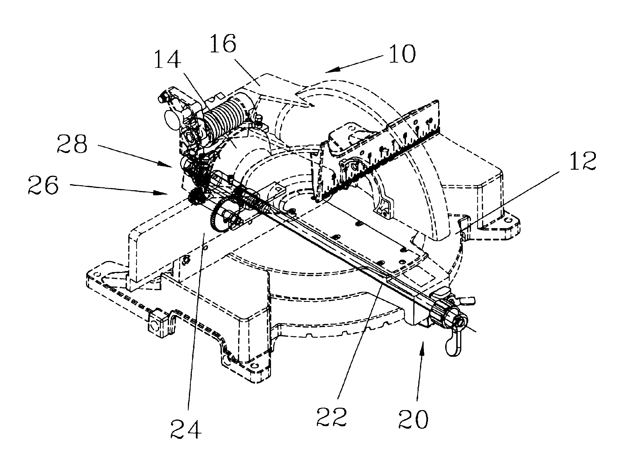
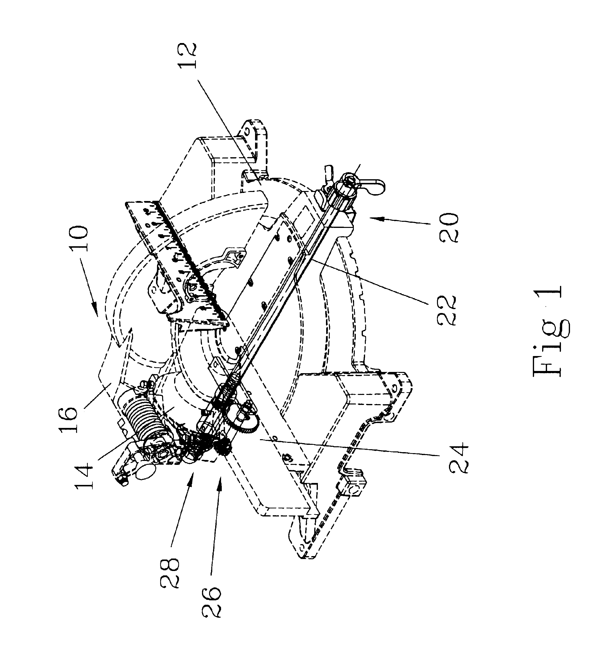
Referring to the drawings and initially to FIG. 1, a circular saw 10 having a saw arm angle adjusting device in accordance with the preferred embodiment of the present invention comprises a base 12, a saw arm 16, and an angle adjusting device 20 for adjusting the inclined angle of the saw arm 16.

The base 12 is a circular body having a side provided with a rotor 14.

The saw arm 16 has a first end pivotally mounted on the rotor 14 of the base 12 and a second end provided with a saw blade (not shown). Thus, the saw arm 16 can be pivoted relative to the base 12 in a vertical manner, and can be rotated with the rotor 14 to deflect in an inclined manner.

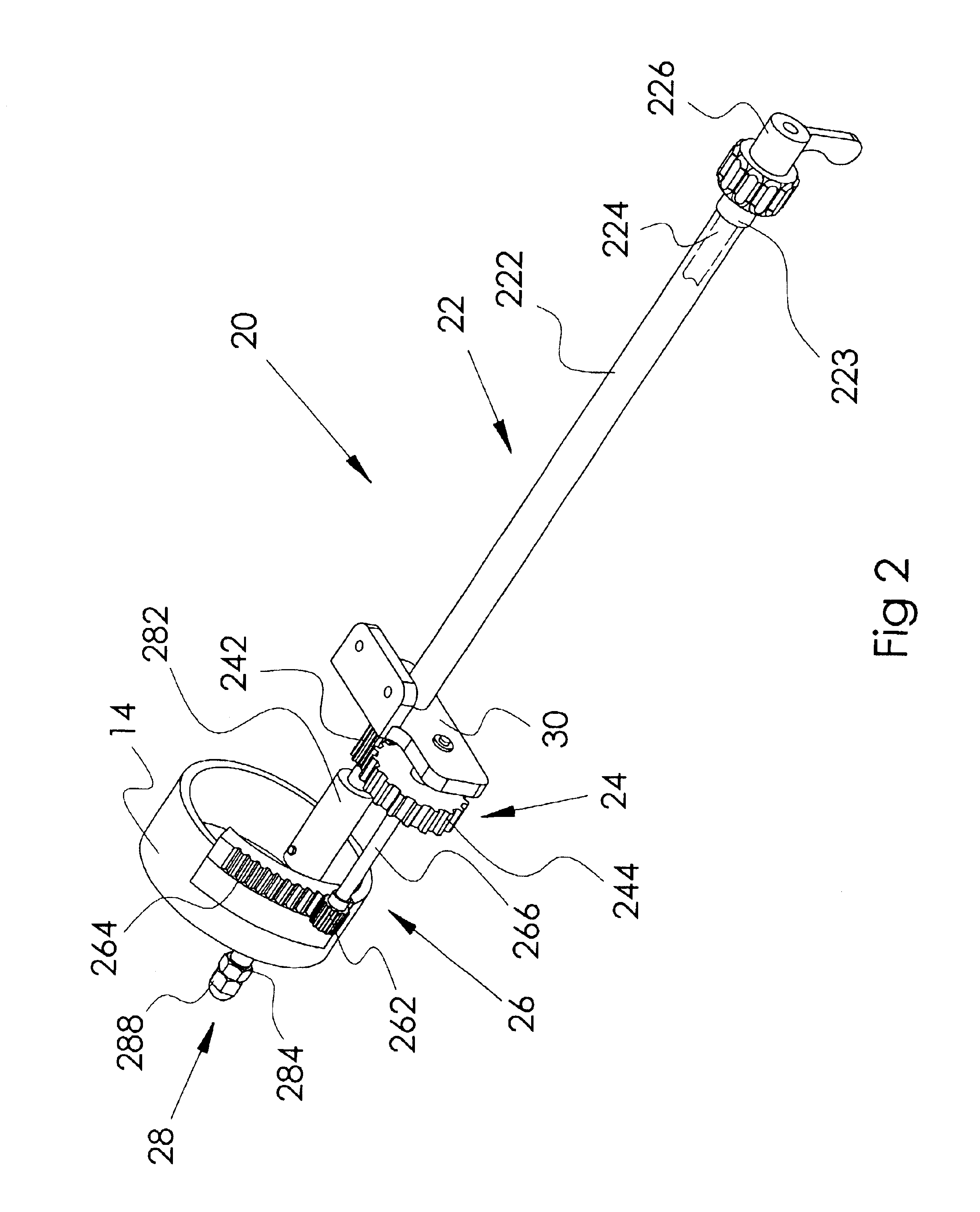
The angle adjusting device 20 is mounted on a bottom face of the base 12, and includes a rod unit 22, a first gear unit 24, a second gear unit 26, and a positioning unit 28.

Referring to FIGS. 2-4, the rod unit 22 includes an outer rod 222, and an inner rod 224 mounted in the outer rod 222. The outer rod 222 has a first end provided with a l...


PUM

PropertyMeasurementUnit
inclined angleaaaaaaaaaa
angleaaaaaaaaaa
arm angleaaaaaaaaaa

Abstract

A circular saw includes a base, a saw arm, and an angle adjusting device. The angle adjusting device includes a rod unit, a first gear unit, a second gear unit, and a positioning unit. The rod unit includes an outer rod, and an inner rod. The first gear unit includes a first drive gear and a first driven gear. The second gear unit includes a second drive gear and a second driven gear. The positioning unit includes a mounting tube, and a positioning bolt. Thus, the inclined angle of the saw arm can be adjusted by the angle adjusting device easily and conveniently, thereby facilitating the user operating the circular saw.

Description

BACKGROUND OF THE INVENTION1. Field of the InventionThe present invention relates to a circular saw having a saw arm angle adjusting device, and more particularly to a circular saw having a saw arm angle adjusting device that can facilitate the user's operation.2. Description of the Related ArtA conventional circular saw in accordance with the prior art comprises a base, a saw arm mounted on the base, and a saw blade mounted on the saw arm. The saw arm may be moved toward the base for cutting the workpiece on the base by the rotating the saw blade. The conventional circular saw also comprises an adjusting device for adjusting the angle of the saw arm relative to the base, so that the saw arm is inclined with the base. Thus, the cutting face of the workpiece may be cut to have an inclined shape. The adjusting device is usually mounted on the rear portion of the saw arm, so that the user has to move to the rear portion of the saw arm, so as to operate the adjusting device, thereby cau...

Claims


Application Information

Patent Timeline
Patent Type & Authority Patents(United States)
IPC IPC(8): B23D45/04B23D45/00B27B5/29B27B5/00
CPCB27B5/29B23D45/044Y10T83/7697Y10T83/7705Y10T83/7788
Inventor CHEN, RUEY ZOU
Owner REXON
Learn More