Multiplier type fishing reel

a multi-type, fishing reel technology, applied in fishing reels, applications, fishing, etc., can solve the problems of difficult to adapt the braking effect of the two brakes to each other, and the fisherman is difficult to set a suitable total braking

Inactive Publication Date: 2005-03-01
PURE FISHING
View PDF6 Cites 5 Cited by
  • Summary
  • Abstract
  • Description
  • Claims
  • Application Information

AI Technical Summary

Benefits of technology

An object of an embodiment of the present invention is to provide a multiplier type fishing reel which has a first and a second brake, and in which the total braking effect of the brakes on the line spool can be set in a simple manner while at the same time the relative braking condition of the two brakes can be automatically adapted to each other.
This solution makes it possible to set the total braking effect of the two brakes in a simple manner by turning the common operating device. By this turning, the adjusting device of the two brakes are made to turn for adjusting the braking effect of the respective brakes on the line spool. The adjusting of the braking effect of one brake is dependent on the adjusting of the braking effect of the other brake, and this dependence is set in advance at the factory by selecting suitable components and dimensions of the components, so that the fisherman does not have to worry about adapting the braking effect of the brakes to each other.
In a preferred embodiment, the operating device and the adjusting device are arranged so that turning of the operating device in one direction makes both the first and the second adjusting device turn for increasing the braking effect of the respective brakes on the line spool, and turning of the operating device in the other direction makes both the first and the second adjusting device turn for reducing the braking effect of the respective brakes on the line spool.

Problems solved by technology

It is very difficult for the fisherman to set a suitable total braking effect and still more difficult to adapt the braking effect of the two brakes to each other.

Method used


Image

  • Multiplier type fishing reel
  • Multiplier type fishing reel
  • Multiplier type fishing reel

Examples


Embodiment Construction

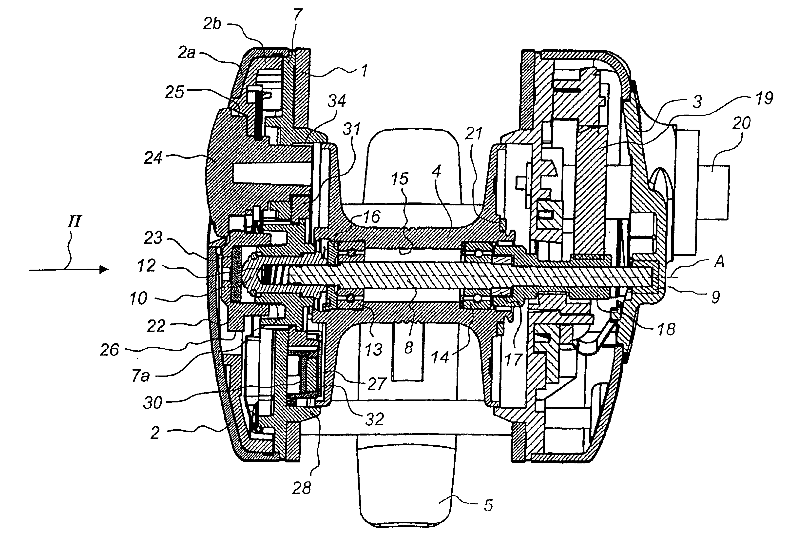
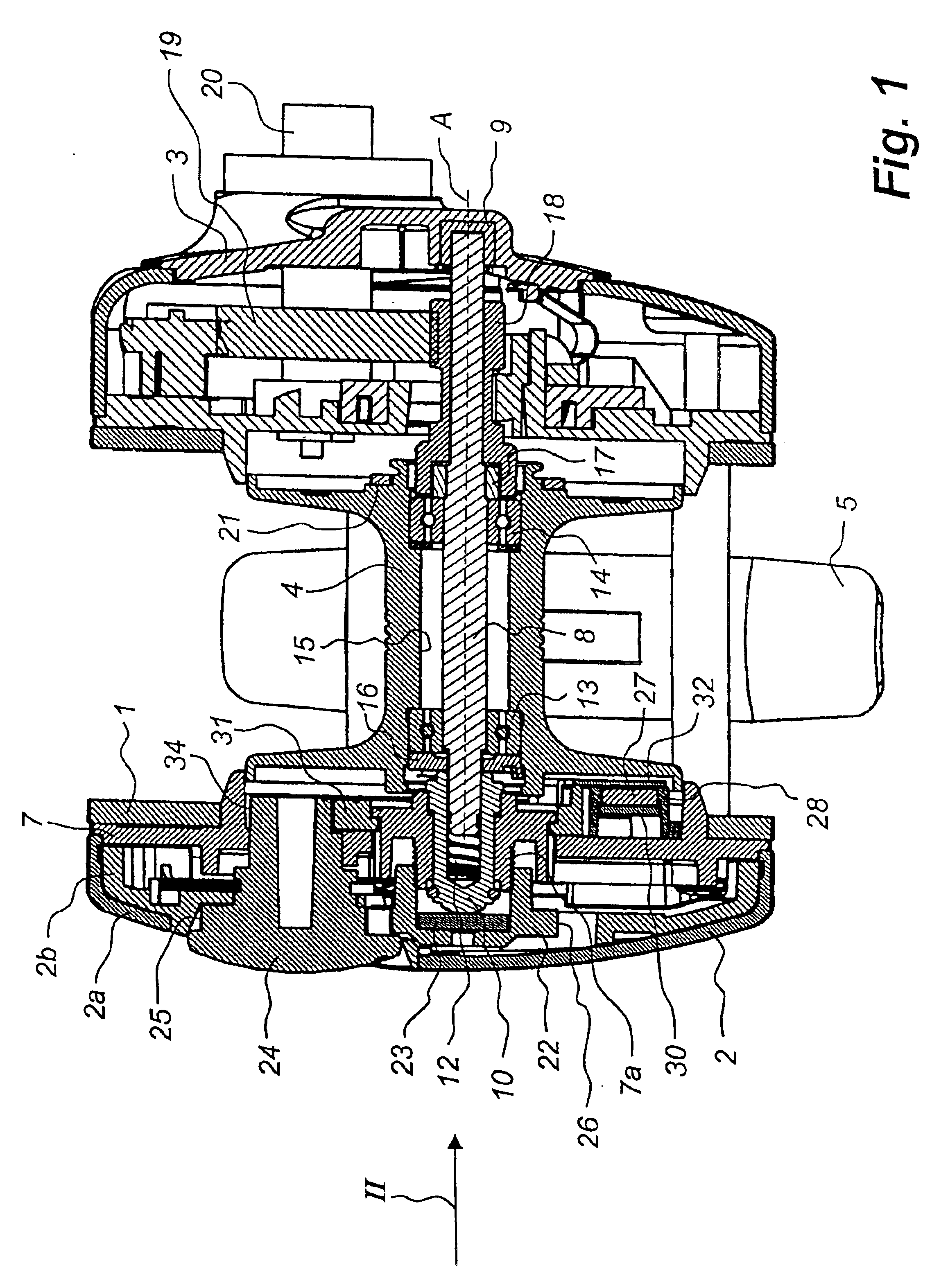
The multiplier type fishing reel shown in FIG. 1 has a frame 1, two side plates 2 and 3, a line spool 4 mounted in the frame 1 for receiving a line (not shown) and a foot 5 for mounting the fishing reel on a fishing rod (not shown).

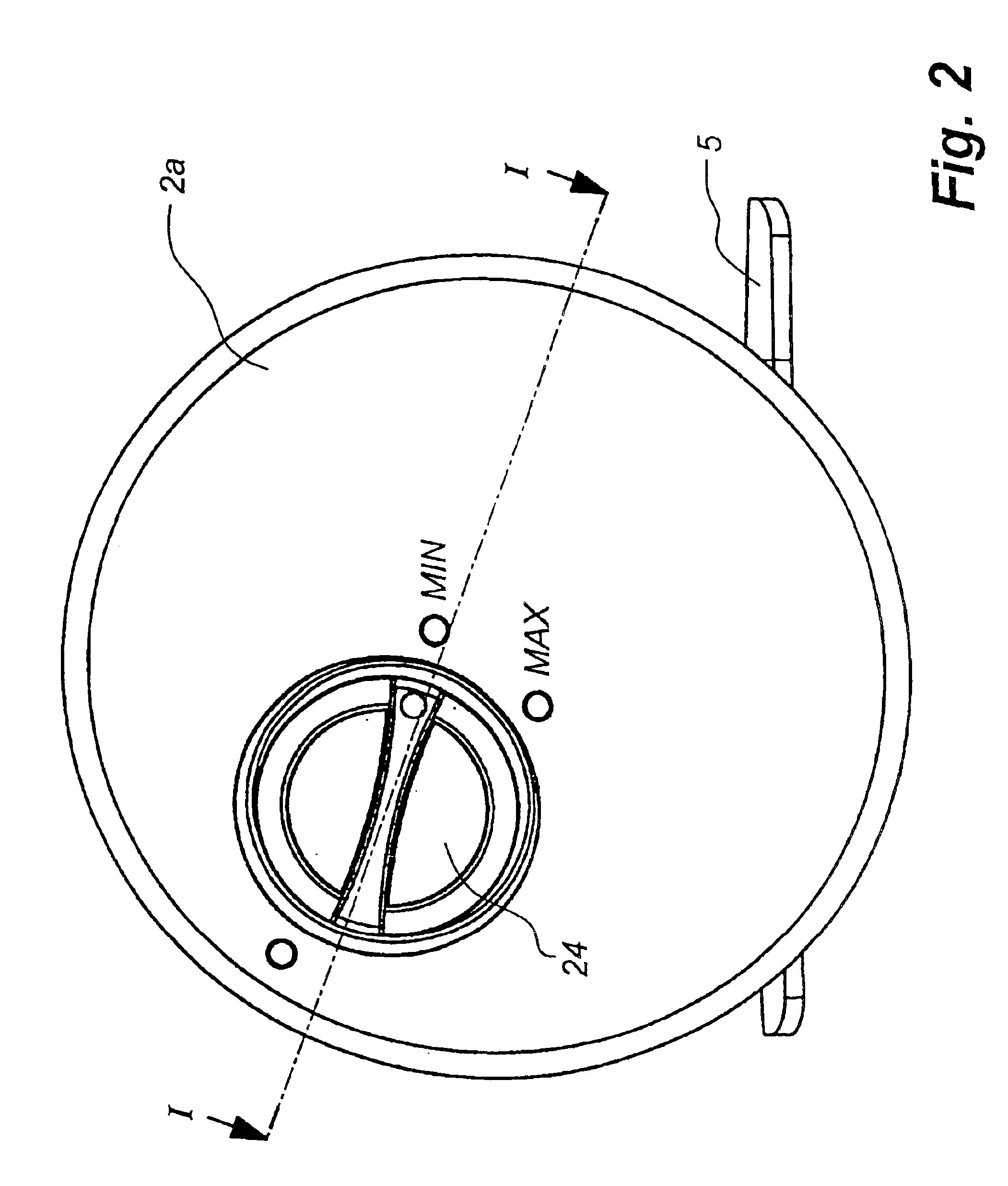
The right side plate 3, which will not be described in detail here, is screwed to the frame 1. The left side plate 2 consists of a cap-shaped outer part 2a and a cap-shaped inner part 2b, to which the outer part 2a is snapped on. The inner part 2b is attached by way of screws 6 (FIG. 3) to a mounting plate 7 which in turn is screwed to the frame 1.

A line spool shaft 8 is at its one end inserted into a cup-shaped sleeve 9 which is fixed in the right side plate 3, and at its other end inserted into a cup-shaped sleeve 10 extending through the mounting plate 7. The sleeve 10 is non-rotatably but axially displaceably mounted in a through hole 11 (FIG. 3) in an externally threaded hub portion 7a projecting to the left and positioned on the mounting plate 7, th...


PUM


Abstract

A multiplier type fishing reel has a frame, two side plates which are mounted on the frame, a line spool which is mounted in the frame and rotatable about an axis of rotation, and a first and a second brake for braking the line spool. The braking effect of the first brake is adjustable with the aid of a first adjusting device which is turnable about an axis parallel to the axis of rotation and the braking effect of the second brake is adjustable with the aid of a second adjusting device which is turnable about an axis parallel to the axis of rotation. The first and the second adjusting devices are arranged in one of the side plates and have respectively a first and a second tooth portion. An operating device, which is turnable about an axis parallel to the axis of rotation, is mounted on said one side plate and has at least one tooth element meshing with both tooth portions to make, in turning of the operating device, respectively the first and the second adjusting device turn for adjusting the braking effect of the respective brakes on the line spool.

Description

FIELD OF THE INVENTIONThe present invention generally relates to a multiplier type fishing reel having a frame, two side plates which are mounted on the frame, a line spool which is mounted in the frame and rotatable about an axis of rotation, a first and a second brake for braking the line spool, the braking effect of the first brake on the line spool being dependent on the speed of rotation thereof and adjustable with the aid of a first adjusting device which is turnable about an axis parallel to the axis of rotation and the braking effect of the second brake on the line spool being independent of the speed of rotation thereof and adjustable with the aid of a second adjusting device which is turnable about an axis parallel to the axis of rotation.The two brakes are used to brake the line spool during casting, thereby to prevent rotation of the line spool at a speed which is higher than the pay-out speed of the line, which usually results in backlash with consequent tangling of the...

Claims


Application Information

Patent Timeline
Patent Type & Authority Patents(United States)
IPC IPC(8): A01K89/0155A01K89/00
CPCA01K89/0155A01K89/01555A01K89/057
Inventor MOOSBERG, BORJE
Owner PURE FISHING
Why Eureka
Try Eureka