Transceiver for LC connector

a technology of transceiver and connector, which is applied in the direction of optics, instruments, optical light guides, etc., can solve the problems of incompatibility of prior art optoelectric modules with early defect detection procedures, high cost of optoelectric modules, and high cost of completion, so as to facilitate testing, reduce cost, and facilitate the effect of testing

Inactive Publication Date: 2005-03-01
TYCO ELECTRONICS LOGISTICS AG (CH)
View PDF5 Cites 26 Cited by
  • Summary
  • Abstract
  • Description
  • Claims
  • Application Information

AI Technical Summary

Benefits of technology

The present invention provides for an optoelectric module that has an optical subassembly that facilitates testing of all of the critical optical alignments and OEDs early in the assembly process before a significant investment of assembly time and materials is made. More specifically, the optoelectric module of the present invention has an optical subassembly which defines the optical path from a fiber in a ferrule to an OED in a unitary, integrally-molded optical block. The integrally-molded optical block also comprises a ferrule-receiving bore at one end of the optical path for holding the ferrule such that the fiber is aligned with the optical path, and a OED-receiving cavity at the other end of the optical path for holding a lead frame such that the OED thereon is substantially aligned or readily alignable with the optical path. This way, a testable optical subassembly, in which all critical optical alignments are fixed, is formed early in the assembly process by simply combining the unitary, integrally-molded optical block with an OED. This has considerable advantages over the prior art designs which require the assembly of multiple components which are typically expensive and difficult to handle. Therefore, it is an advantage of the testable optical subassembly of the present invention that, if a faulty optical subassembly is detected, remedial action can be performed without extensive disassembly or subassembly can be scrapped with a minimum investment of time and materials.
One aspect of the present invention is an easily-assembled, testable optical subassembly for transmitting optical signals between a fiber held in a ferrule and an OED. In a preferred embodiment, the testable optical subassembly comprises a unitary structure of an optically-clear moldable material having at least the following features: (a) an optical path for transmitting optical signals between the fiber and the OED; (b) a ferrule-receiving bore for receiving the ferrule and aligning the fiber held therein to the optical path; and (c) an OED-receiving cavity for receiving a lead frame and aligning the OED mounted thereon to the optical path in one or more axes.

Problems solved by technology

Optoelectric modules tend to be expensive and there exists a need to reduce costs associated therewith.
Early detection of a defective subassembly of the module can save costs that would have been incurred to complete the module, e.g. costs of additional assembly time and / or additional components.
For various reasons, prior art optoelectric modules are not compatible with early defect detection procedures.
Specifically, prior art modules tend to require the assembly of numerous, difficult-to-assemble components to obtain a testable subassembly.
Typically, these components represent the most expensive components of the module and require the most time and care to assemble.
For example, the TO cans typically used in prior art modules are incompatible with most automated pick-and-place assembly operations and they lack reference surfaces to facilitate passive alignment.
Therefore, TO cans must be handled manually and actively aligned by hand which is expensive and does not lend itself to high volume production.
Therefore, TO cans increase the cost of the testable subassembly.

Method used


Image

  • Transceiver for LC connector
  • Transceiver for LC connector
  • Transceiver for LC connector

Examples


Embodiment Construction

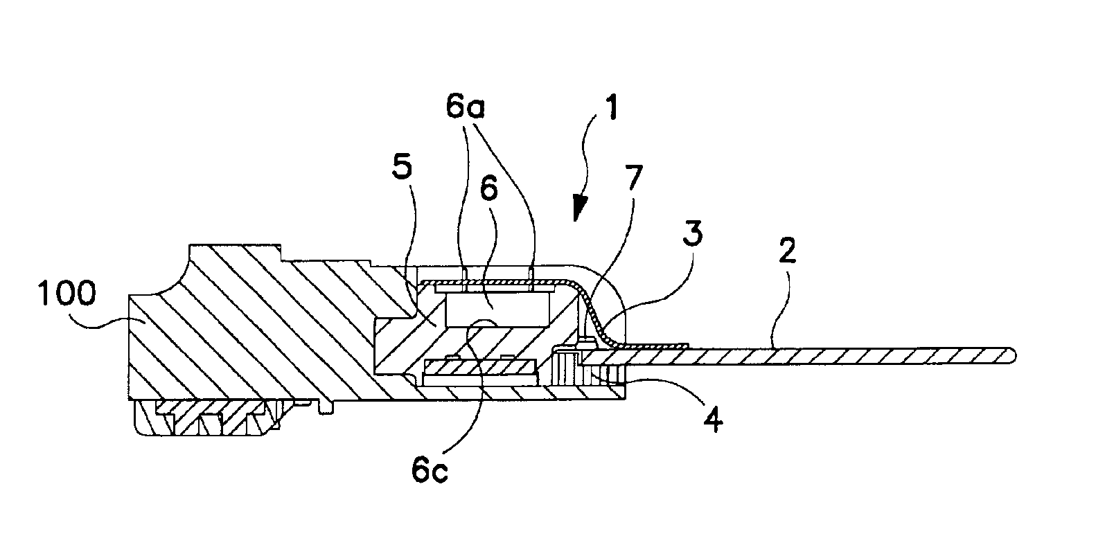
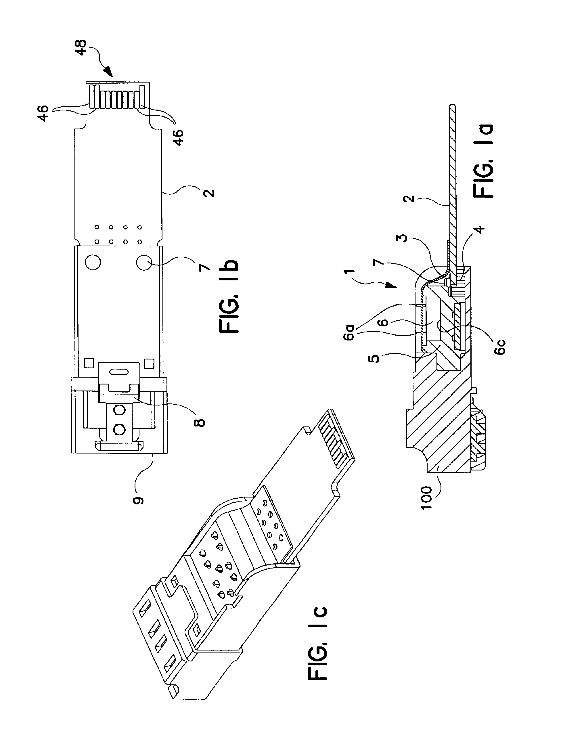
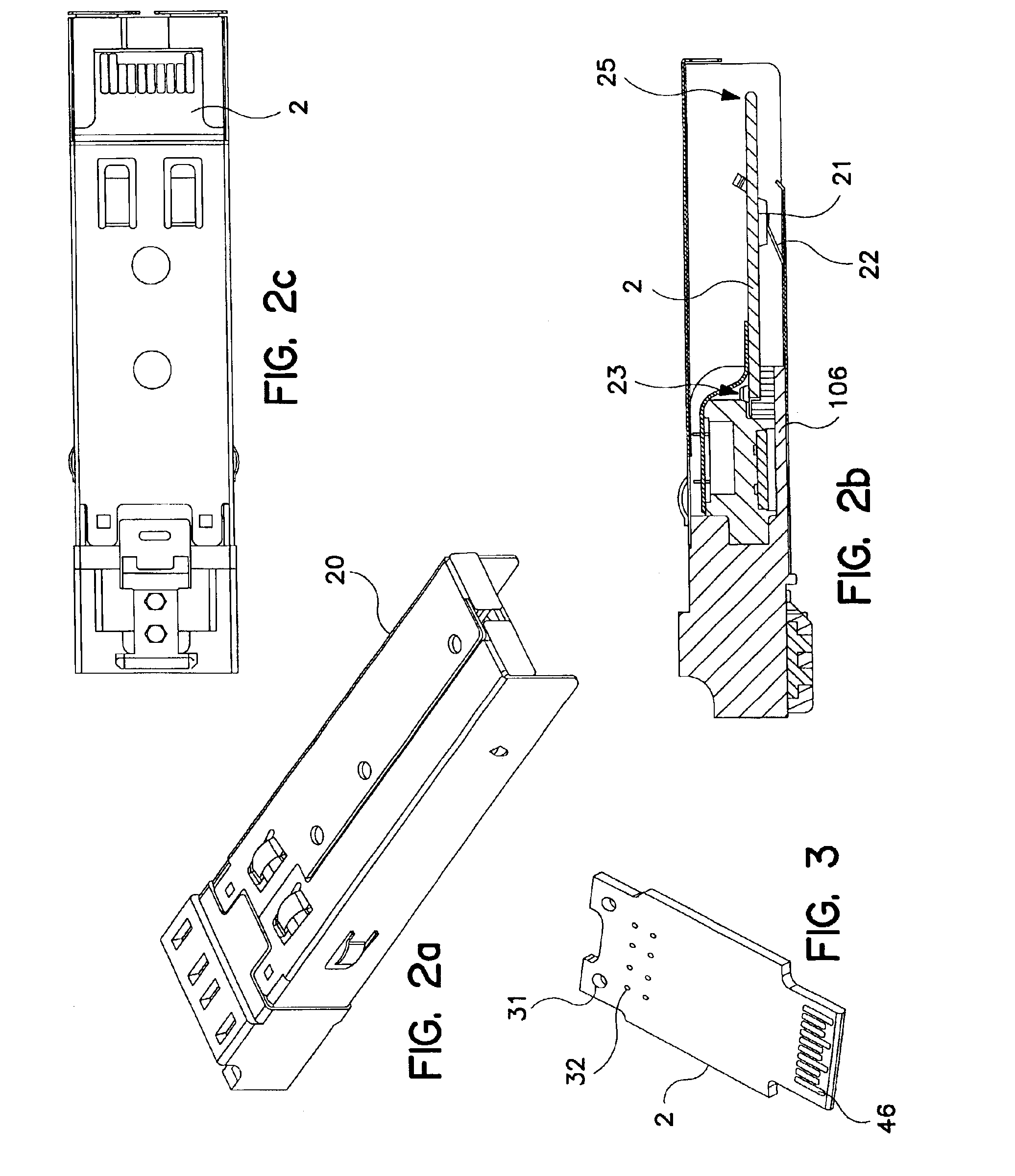
FIGS. 1a-c are cross-sectional, bottom and perspective views of a module 1 in accordance with the present invention. The module 10 is configured to be mounted in a variety of host systems including for example, routers, computers, switches, bridges, and I / O cards. In general, the module may be used in any application requiring an interface between electrical and optical signals. As shown in FIG. 1a, the module 1 basically comprises a testable optical subassembly which in turn comprises an optical block 5 and opto-electric devices (OEDs) 6. The testable optical subassembly is combined with other components which are herein refereed to as post-test-assembly components and which include a printed circuit board 2 and a housing 20 (FIG. 2a). These components are addressed in greater detail below.

Testable Optical Subassembly

An important aspect of the present invention is the testable optical subassembly. The testable optical subassembly essentially involves only two components—namely, the...


PUM


Abstract

A testable optical subassembly comprising a unitary structure of an optically-clear moldable material having at least the following features: (a) an optical path for transmitting optical signals between a fiber and an optoelectric device (OED); (b) a ferrule-receiving bore for receiving a ferrule and aligning a fiber held therein to the optical path; and (c) an OED-receiving cavity for receiving a lead frame and aligning an OED mounted thereon to the optical path along one or more axes.

Description

FIELD OF INVENTIONThe present invention is related generally to opto-electric devices. More specifically, the present invention relates to transceiver devices for use with an LC-type connector.BACKGROUND OF THE INVENTIONAn important subsystem of an optical telecommunication system is the opto-electric interface which converts signals between the optical domain and the electrical domain. Typically, the opto-electric interface comprises some kind of opto-electric device (OED) for either transmitting or receiving optical signals. OEDs are commonly packaged in “TO can” assemblies which comprise a cap and a header assembly. The header assembly can be a hybrid microelectronic assembly which includes the OED plus one or more integrated circuits (ICs) or passive components.In addition to the OED, a typical opto-electric interface comprises a printed circuit board or substrate containing the necessary circuitry to operate the OED, and a connector interface for interfacing with an optical con...

Claims


Application Information

Patent Timeline
Patent Type & Authority Patents(United States)
IPC IPC(8): G02B6/42
CPCG02B6/4292G02B6/4246G02B6/4245G02B6/4277G02B6/4281G02B6/4284
Inventor EDWARDS, PHILIP J.LEVIN, BRADLEY S.O'TOOLE, MICHAEL M.VANDENBERG, JOSEPH L.XU, LEE L.
Owner TYCO ELECTRONICS LOGISTICS AG (CH)
Why Eureka
Try Eureka