Hydraulically stowable and extendable ramp

a technology of hydraulic stowage and extendable ramps, which is applied in the direction of transportation items, loading/unloading vehicle arrangment, refuse collection, etc., can solve the problems of multiple actuators, ineffective systems, heavy ramps, etc., and achieve the effect of simple maintenance and operation system and minimal equipment utilization

a technology of hydraulic stowage and extendable ramps, which is applied in the direction of transportation items, loading/unloading vehicle arrangment, refuse collection, etc., can solve the problems of multiple actuators, ineffective systems, heavy ramps, etc., and achieve the effect of simple maintenance and operation system and minimal equipment utilization

US6860702B1Inactive Publication Date: 2005-03-01BANKS RAYMOND L

Image

  • Hydraulically stowable and extendable ramp
  • Hydraulically stowable and extendable ramp
  • Hydraulically stowable and extendable ramp

Examples


Embodiment Construction

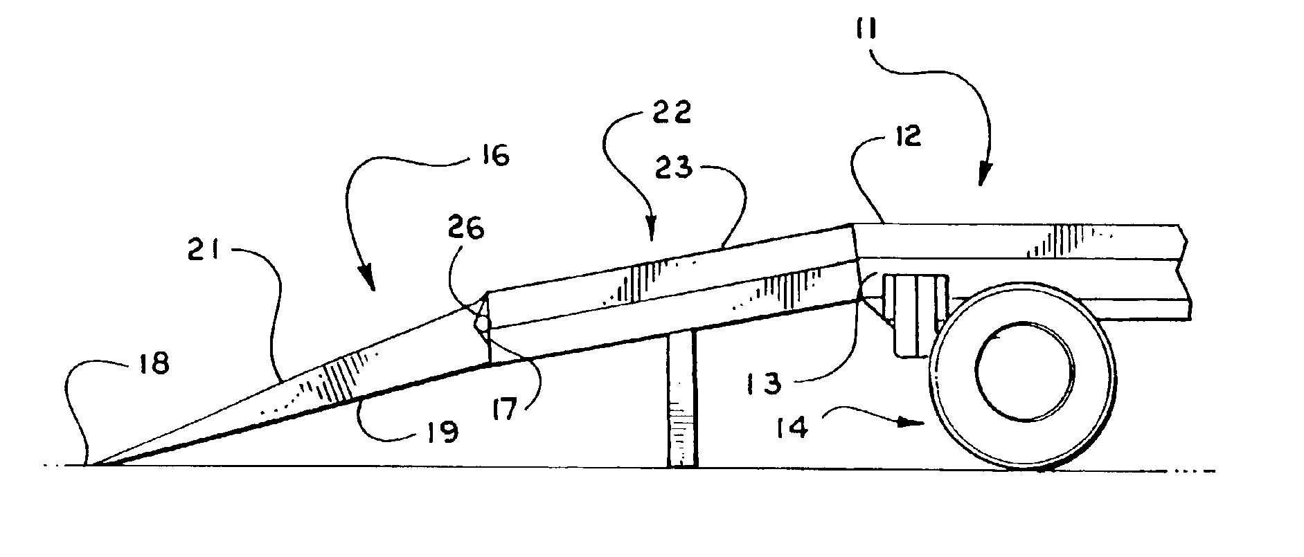
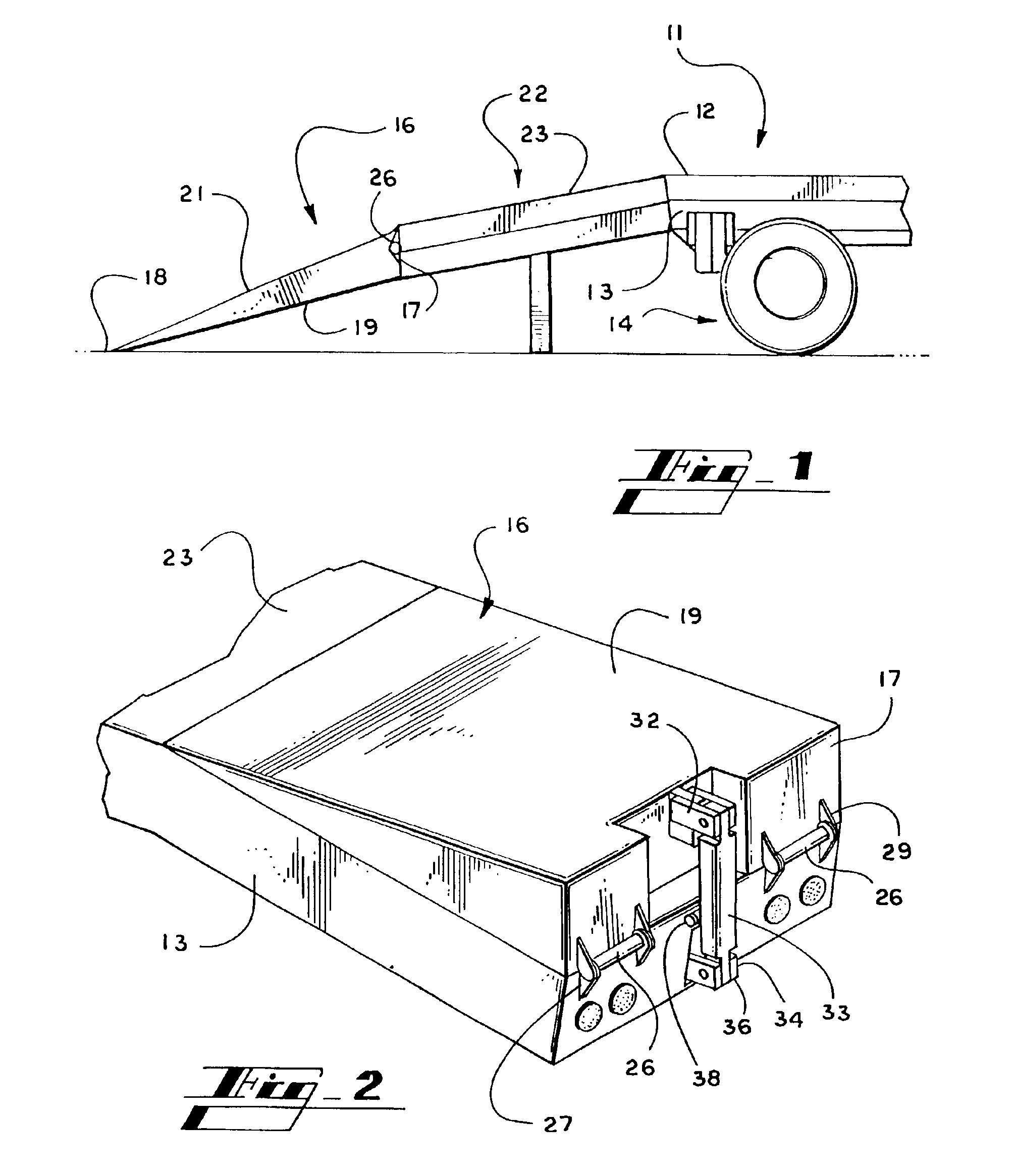
Referring to the drawings for a clearer understanding of the invention it is to be understood that the present invention is depicted as an improvement to a draft trailer and in the drawings the draft trailer is depicted as a beavertail trailer, however the principles of the invention may be applied to any draft trailer which has a source of hydraulic power such as from the associated tractor to operate the mechanism. Referring to FIG. 1 it may be seen that trailer 11 is a flatbed trailer having a bed 12 mounted atop a frame 13 and supported on a set of wheels 14 which are conventionally attached using appropriate bogies or like connections. In general, the frame is conventional as well comprising a plurality of longitudinal I beams and transverse girders.

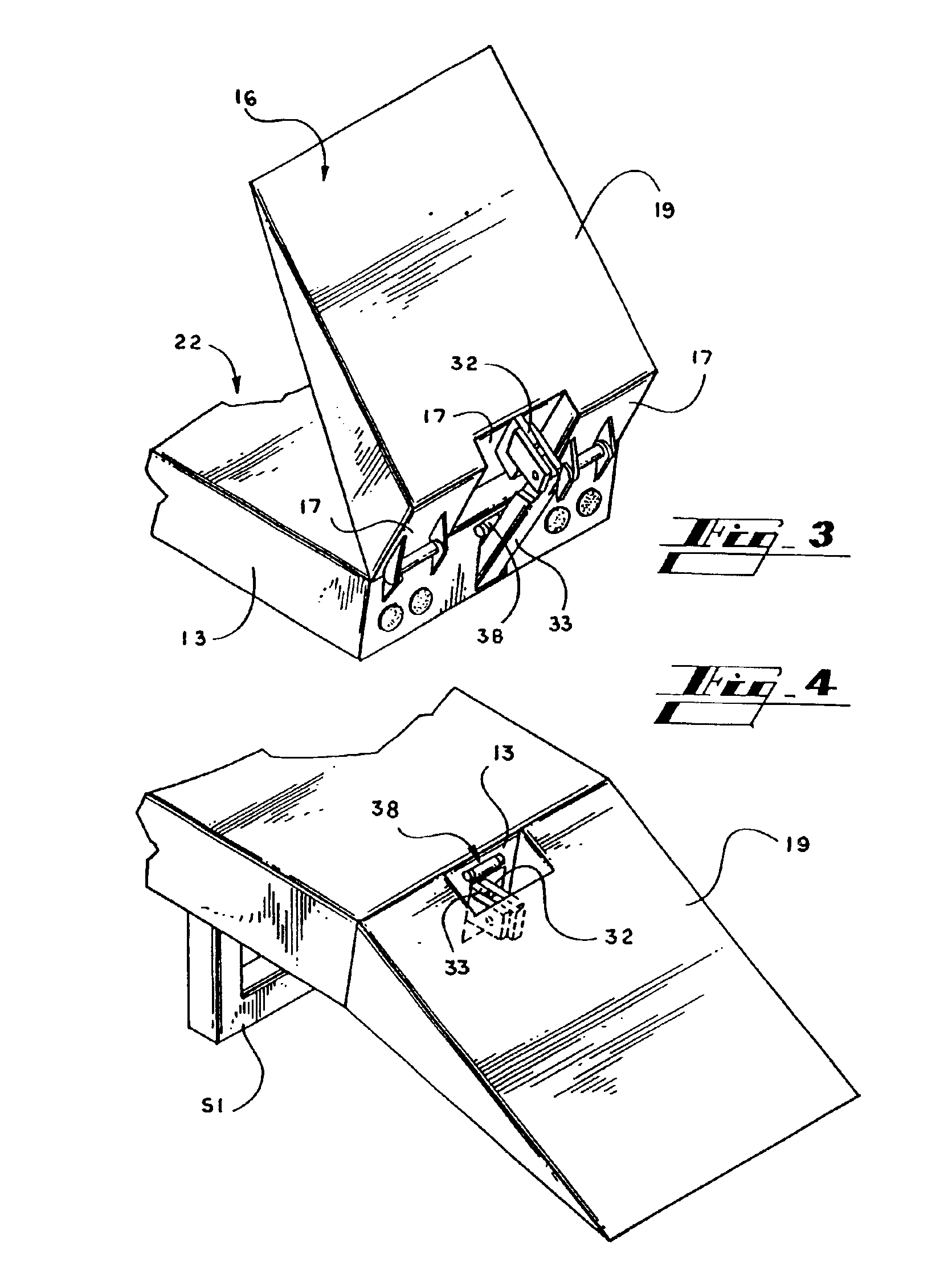
Ramp 16 is a generally wedge shaped weldment tapering from a base plate 17 to a nose 18. A flat deck plate 19 and a rampway 21 extend from base plate 17 and intersect at nose 19. In the beavertail configuration, the beavertail 22 ha...


PUM


Abstract

A linear hydraulic actuator mounted to the frame of a trailer to drive a slider longitudinally and return the slider to its rest position urging a ramp about a horizontal transverse axis such that the ramp moves between a stowed position and an extended position. The slider is operatively connected to a parallel rod which is connected to a bell crank on a pivotally mounted stand beneath the end of the trailer such that as the slider moves the stand is concomitantly urged between a stowed position and a deployed ground engaging position.

Description

FIELD OF THE INVENTIONThe present invention relates to the field of draft trailers and more particularly to transport trailers used to transport equipment or other vehicles. In greater particularity, these trailers usually include a flat bed, and may include an inclined platform known as a beaver tail, and a ramp attached to the beaver tail platform. The invention further relates to the mechanism for stowing and extending such ramps from the ends of such trailers.BACKGROUNDFlatbed trailers and the like used to transport heavy equipment and large vehicles are necessarily built with considerable attention to the strength and durability aspects. Consequently, the components are well constructed and employ a relatively large mass of material. As is well known, wheeled equipment and vehicles are driven on to the trailer over ramps that are pivotally mounted to the rear of the trailer. These ramps are heavy and difficult to move from an extended position to a stowed position. Accordingly,...

Claims


Application Information

Patent Timeline
01 Mar 2005
Publication
US6860702B1
IPC
B60P1/00; B60P1/43
CPC
B60P1/438; B60P1/43
Inventors
BANKS, RAYMOND L.