
Method for forming composite parts from volatile-emitting materials using breathable tooling

a technology of volatile-emitting materials and tooling, which is applied in the field of forming and curing composite materials, can solve the problems of low damage tolerance, composite materials with relatively high fabrication costs, and low damage tolerance, and achieve the effect of dimensional toleran

Inactive Publication Date: 2005-03-01
THE BOEING CO
View PDF50 Cites 28 Cited by
  • Summary
  • Abstract
  • Description
  • Claims
  • Application Information

AI Technical Summary

Benefits of technology

The present invention is a method and apparatus for forming composite parts from composite materials that produce large volumes of volatiles during processing. The invention allows volatiles to be drawn away from the composite material during processing, while allowing dimensional tolerances to be maintained.
The invention allows high-quality composite parts to be formed of composite materials that emit a large volume of volatiles during processing. The invention is not limited to composite parts having simple geometries. Nor is the invention limited to the formation of composite materials in which dimensional tolerances on only one surface of the composite part are important. The invention may be used with autoclave, press or other methods of processing.

Problems solved by technology

Some of the drawbacks to using composite materials have been their relatively high fabrication costs and low damage tolerance.
Generally, it has been difficult to produce parts formed of high strength composite materials at the same cost and having the same damage tolerance as comparable metal parts.
Another disadvantage of composite materials in some applications is their relatively low temperature tolerance.
Most widely used high-strength fiber reinforced composite materials are not usable above 300° F.
In addition, several of the new composite systems emit large quantities of gaseous volatiles during processing.
The high temperatures and pressures required for processing and the off-gassing of volatiles increases the difficulty in processing the new materials.
Failure to draw off the volatiles during processing results in voids or areas of porosity in the formed composite parts.
Past methods used to draw off volatiles limit the ability to fabricate complex parts from volatile-producing materials.
However, if dimensional tolerances must be maintained throughout the part, it is generally not possible to use a cloth breathing material adjacent the composite material during processing.
When rigid matched tooling is used, volatiles emitted become trapped within the composite material during processing.
The use of cloth breathing materials between the tool and the composite material created a number of problems.
The cloth breathing material made it difficult, and in most circumstances impossible, to control dimensional tolerances on the surfaces of the formed composite part.
Such pressure variations resulted in resin-rich, resin-poor, or porous regions within the formed composite part.

Method used


Image

  • Method for forming composite parts from volatile-emitting materials using breathable tooling
  • Method for forming composite parts from volatile-emitting materials using breathable tooling
  • Method for forming composite parts from volatile-emitting materials using breathable tooling

Examples


Embodiment Construction

The present invention is a method and apparatus to form and cure composite materials that produce large quantities of volatiles during processing. The invention is described below with respect to a preferred embodiment used to form a sine wave spar. However, the method and apparatus of the invention may be used to form a wide variety of composite structures. The preferred embodiment is also described with respect to the use of DuPont's K-IIIB material system. However, the invention may be used with other composite material systems.

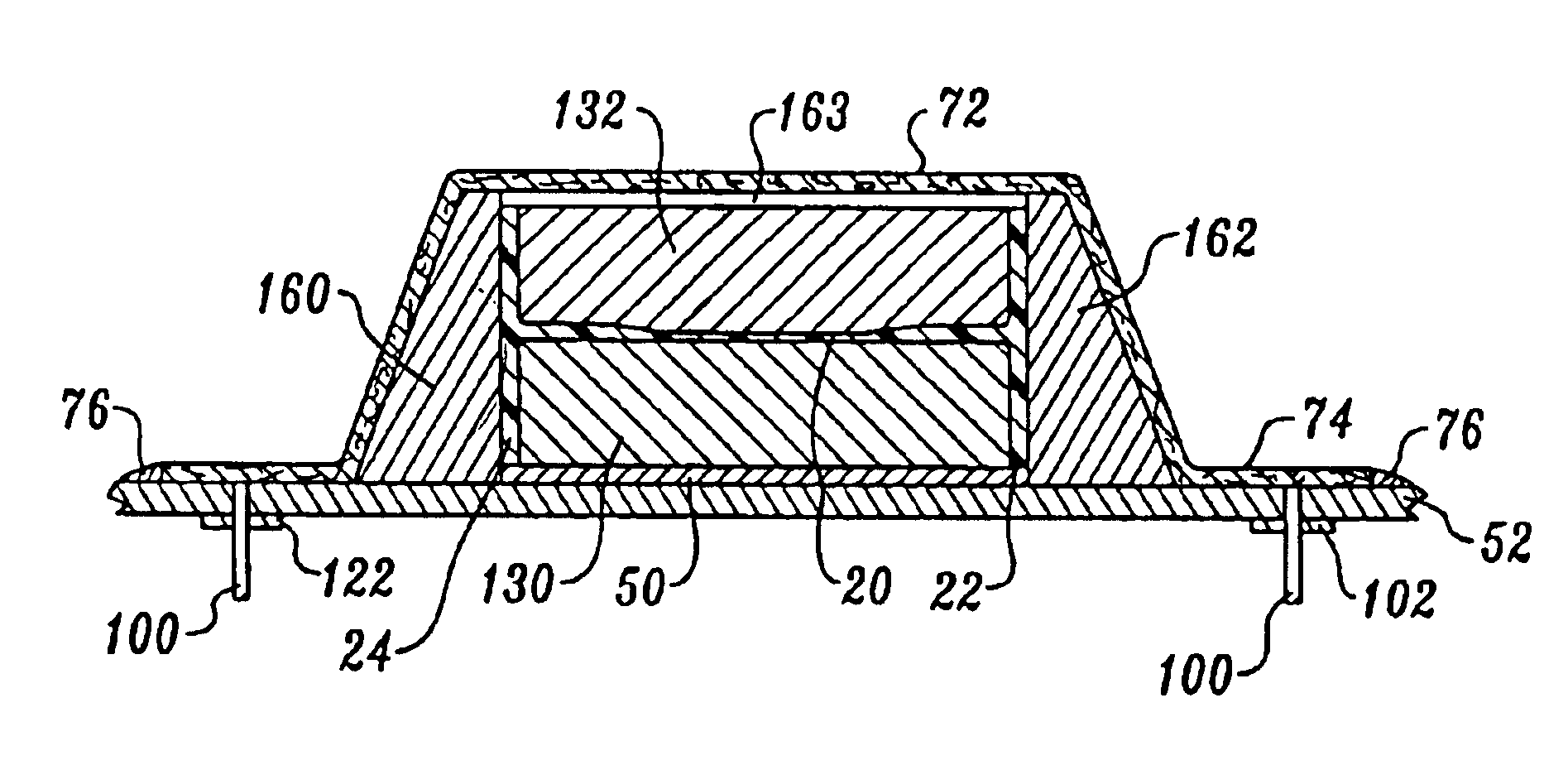
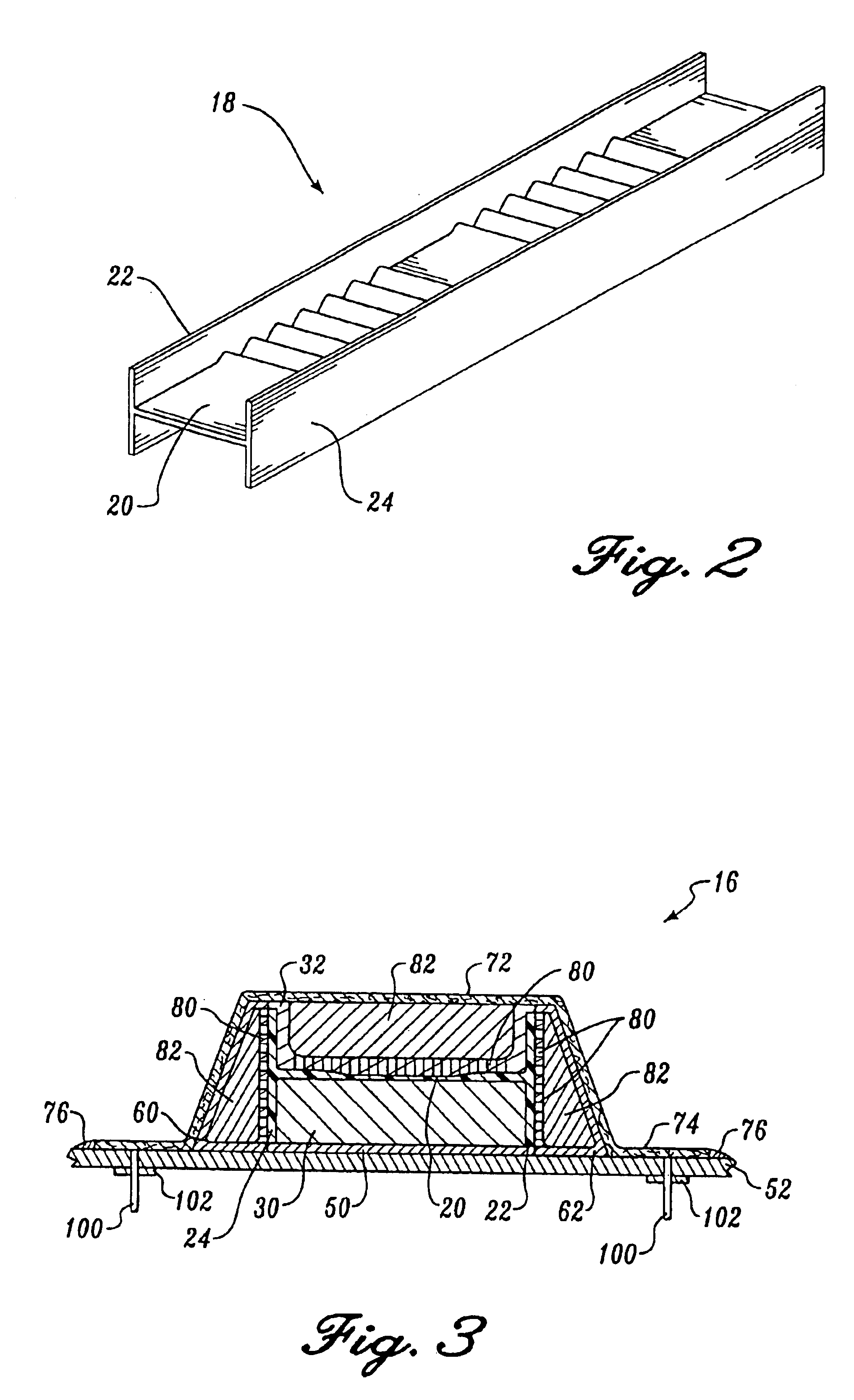
FIG. 2 illustrates a sine wave spar 18 fabricated using a breathable tooling concept (FIG. 3) according to the invention. As best illustrated in FIG. 2, the sine wave spar 18 is an I-beam having a sine wave central web 20 that extends between left and right spar caps 22 and 24, respectively.

In the preferred embodiment, it is important to maintain dimensional tolerances on the surfaces of the spar caps 22 and 24 and central web 20. In order to maintain such...


PUM

PropertyMeasurementUnit
Fractionaaaaaaaaaa
Temperatureaaaaaaaaaa
Forceaaaaaaaaaa

Abstract

A method and apparatus for curing composite materials that emit large volumes of volatiles during processing. The apparatus includes tooling having a rigid forming surface contoured to the shape of the formed composite part. A plurality of passages extend from the forming surface through the tooling. The passages are in fluid contact with an exhaust port. A composite workpiece is laid up and placed adjacent the forming surface. The apparatus includes a heater that heats the composite workpiece to temperatures at which volatiles are emitted. An evacuation system draws the volatiles away from the composite workpiece through the passages in the tooling and out of the exhaust port. One embodiment of tooling according to the invention is used to form a sine wave spar. The tooling includes upper and lower tool inserts upon which U-shaped composite channels are formed. The upper and lower tools are placed adjacent to each other to form the web of the spar. Cap strips are placed on either side of the joined U-shaped channels. Side rail tools are then placed adjacent the cap strips. A breather cloth is placed over the tools and the entire assembly is placed within a vacuum bag. The assembly is then placed within an autoclave and connected to the vacuum exhaust of the autoclave. During processing, volatiles are drawn away from the composite workpiece through the passages in the tooling using the vacuum exhaust.

Description

FIELD OF THE INVENTIONThe invention relates to a method and apparatus for forming and curing composite materials, and more particularly to the forming and curing of composite materials that produce large amounts of volatiles during processing.BACKGROUND OF THE INVENTIONThe use of high strength fiber reinforced composite materials in the manufacture of aircraft and other lightweight structures has increased steadily since the introduction of such materials. Composite materials have a high strength-to-weight ratio and stiff-ness. These properties make composite materials attractive for use in the design of lightweight structures. Some of the drawbacks to using composite materials have been their relatively high fabrication costs and low damage tolerance. Generally, it has been difficult to produce parts formed of high strength composite materials at the same cost and having the same damage tolerance as comparable metal parts. Another disadvantage of composite materials in some applica...

Claims


Application Information

Patent Timeline
IPC IPC(8): B29C33/10B29C70/04B29C70/54B29C37/00B29C33/38
CPCB29C33/10B29C43/021B29C70/54B29C43/12B29C33/3814B29C37/006B29L2031/003B29C70/34B29C2043/3644B29K2105/0854B29D99/0007
Inventor MCCARVILLE, DOUGLAS A.SWEETIN, JOSEPH L.MEDOFF, IRWIN
Owner THE BOEING CO
Learn More