
Self-stiffened skin for aircraft fuselage including stringers with a closed section and associated manufacturing method

a manufacturing method and closed-section technology, applied in the field of self-stiffened skin for aircraft fuselage including stringers with a closed-section and associated manufacturing methods, can solve the problems of high cost, large precision required for use of such a mandrel with grooves, and complex implementation of stringers, so as to achieve low cost, relaxed dimensional tolerances for stringer manufacturing, and simple implementation

Active Publication Date: 2016-09-20
AIRBUS OPERATIONS (SAS)
View PDF14 Cites 0 Cited by
  • Summary
  • Abstract
  • Description
  • Claims
  • Application Information

AI Technical Summary

Benefits of technology

[0029]By this means the invention enables the use of a supporting structure with grooves for the stringers to be avoided. The supporting structure used in the method according to the invention may thus be of low cost. In addition, the dimensional tolerances for the manufacture of the stringers may be relaxed.
[0030]The manufacturing method according to the invention is thus particularly simple to implement, and inexpensive.
[0034]Installation of such an inner skin enables the self-stiffened skin obtained on conclusion of the present method to be given optimal cohesion. This notably enables the separation of this self-stiffened skin and the supporting structure to be facilitated.
[0058]Each cut-out made in this manner provides access to the interior of the corresponding stringer, which notably facilitates inspection of the condition of the stringer during subsequent maintenance operations.
[0060]In a particularly advantageous manner the invention allows a fuselage section of the integral type, also called a “full barrel” section, to be manufactured.
[0065]This fuselage structure has the advantage that it can be produced easily and at a reduced cost by means of a method of the type described above.

Problems solved by technology

The positioning of the stringers requires sophisticated equipment, and is generally complex to implement, in particular when a monobloc self-stiffened skin is manufactured.
However, the use of such a mandrel with grooves requires great precision when manufacturing the stringers and machining of the grooves of the mandrel.
In addition, it is in practice difficult to hold each stringer in position in its associated groove until the stringer is covered by a strip of prepreg.
The method thus proves complex, lengthy and expensive to implement.

Method used


Image

  • Self-stiffened skin for aircraft fuselage including stringers with a closed section and associated manufacturing method
  • Self-stiffened skin for aircraft fuselage including stringers with a closed section and associated manufacturing method
  • Self-stiffened skin for aircraft fuselage including stringers with a closed section and associated manufacturing method

Examples


Embodiment Construction

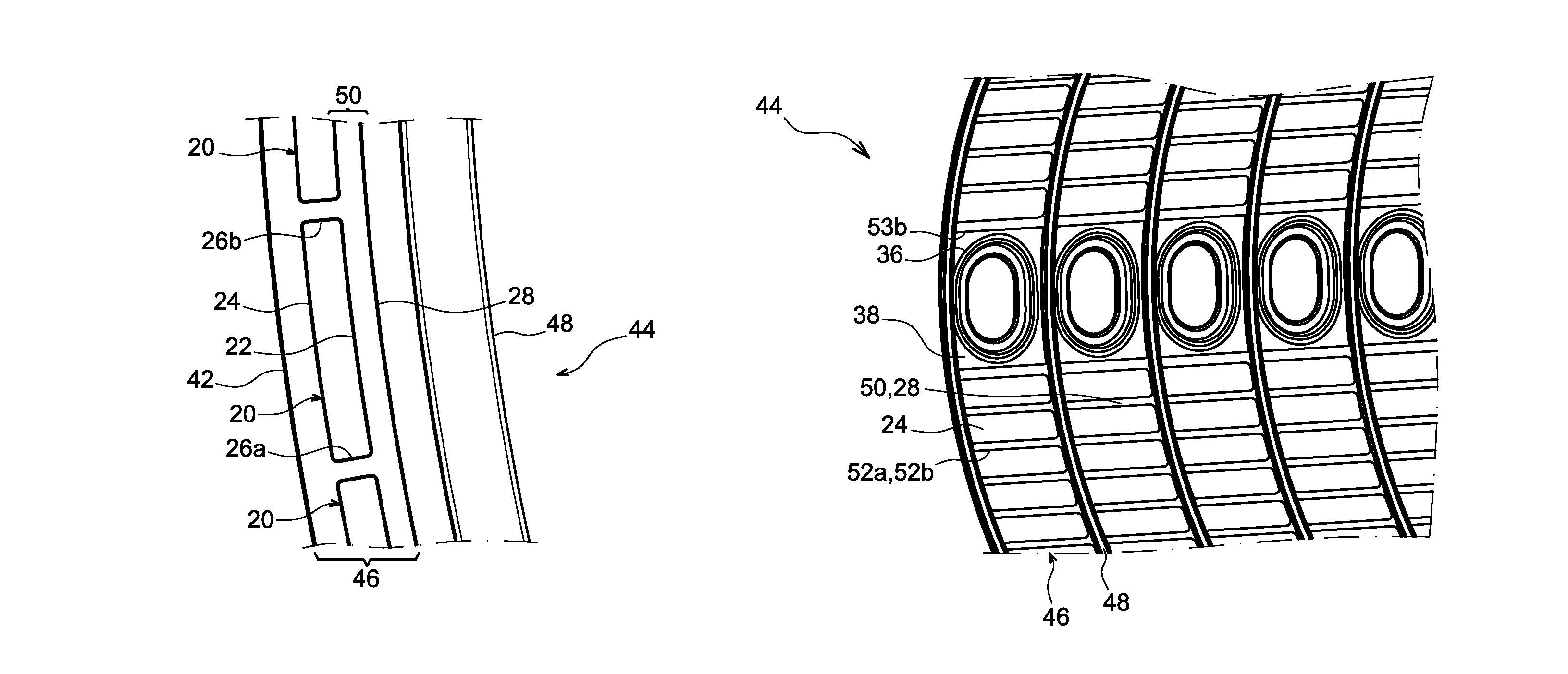
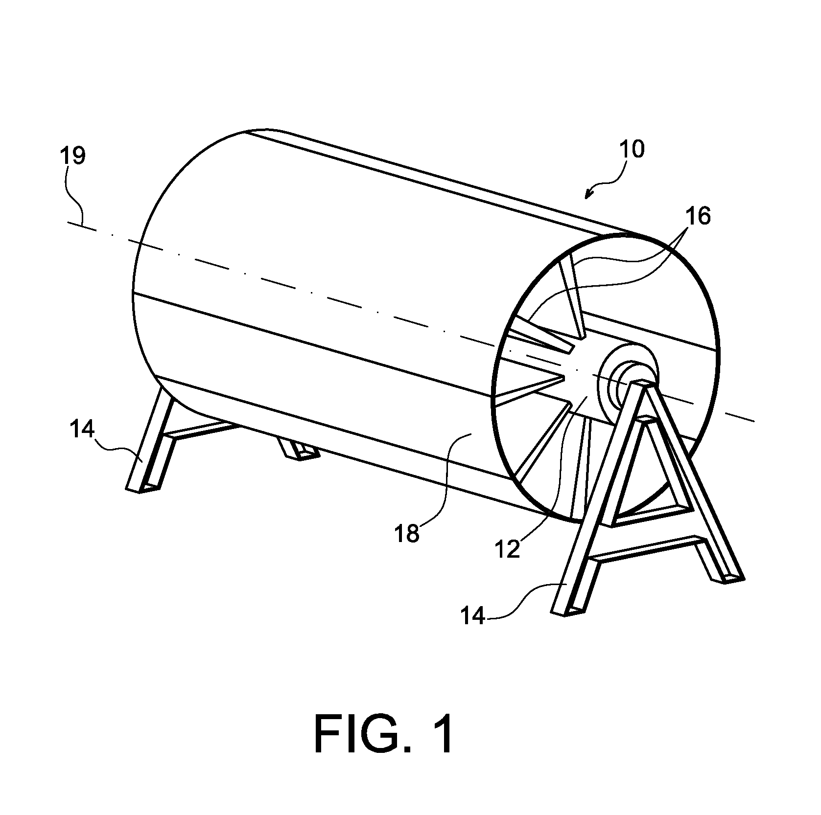
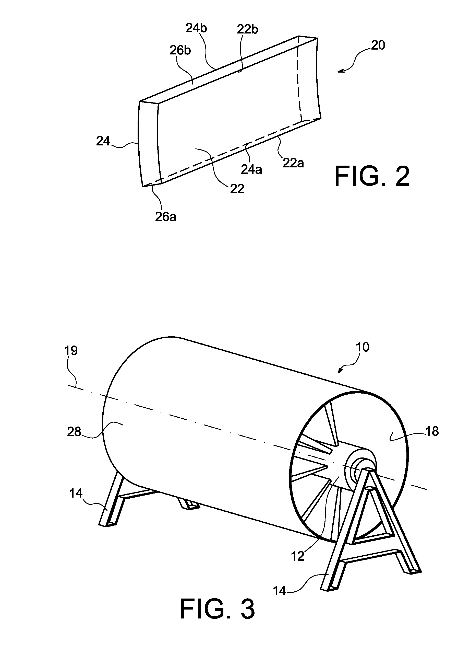
[0094]FIGS. 1 to 6 illustrate a method for manufacturing a structure for an aircraft fuselage according to a preferred embodiment of the invention, in a special case in which said structure is a composite material self-stiffened skin, of the monobloc type, i.e., forming a structure with a closed section, also called a “full barrel” structure. In the illustrated example this self-stiffened skin thus has the shape of a cylinder of revolution.

[0095]The term “composite material” is understood to mean a material formed from strengthening fibers, such as carbon or glass fibers, embedded in a hardened resin, such as epoxy.

[0096]The method firstly includes the preparation of a supporting structure, which in the illustrated example has the form of a mandrel 10, as illustrated in FIG. 1.

[0097]This mandrel 10 globally includes a central shaft 12 supported by two trestles 14, and from which radiate spokes 16 supporting an outer wall having a cylindrical shape, defining an outer surface 18 of th...


PUM

PropertyMeasurementUnit
cylindrical shapeaaaaaaaaaa
shapeaaaaaaaaaa
massaaaaaaaaaa

Abstract

Simplification of the manufacture of composite material fuselages for aircraft, as well as mass reduction of fuselage sections and space optimization inside such fuselage sections. To accomplish this, it is proposed to use stringers of a new type which have a closed transverse section, and which are thus able to be self-positioned relative to one another by being positioned edge-to-edge on a stringer supporting structure, such as the outer surface of a mandrel. The installation of the stringers in grooves of conjugate shape is by this means made unnecessary. The stringers have cut-outs located between circumferential frames, and are able to house utility systems.

Description

CROSS-REFERENCES TO RELATED APPLICATIONS[0001]This application claims the benefit of the French patent application No. 1262947 filed on Dec. 28, 2012, the entire disclosures of which are incorporated herein by way of reference.BACKGROUND OF THE INVENTION[0002]The invention also relates to a method for manufacturing a section of an aircraft fuselage including a self-stiffened skin produced by means of the above method.[0003]The invention also relates to such a fuselage section, and also to an aircraft which including the same, such as an airplane.[0004]In the present description the term “section” may designate any type of aircraft section, including a nose cone or tail cone.[0005]Aircraft fuselages must be able to withstand the loads caused by pressurization and the loads transmitted by the engines.[0006]To this end, the fuselages habitually include circumferential frames, also called “orbital frames”, together with an aerodynamic skin, sometimes called a “self-stiffened skin”, atta...

Claims


Application Information

Patent Timeline
Patent Type & Authority Patents(United States)
IPC IPC(8): B64C1/06B29D99/00B64C1/12B64C1/00
CPCB64C1/068B29D99/0014B64C1/064B64C1/12B64C2001/0072Y02T50/433Y10T156/1052Y10T428/13Y02T50/40
Inventor LIEVEN, PATRICKDELAHAYE, ROMAIN
Owner AIRBUS OPERATIONS (SAS)
Learn More