
Surface acoustic wave filter

a surface acoustic wave and filter technology, applied in the direction of impedence networks, electrical equipment, piezoelectric/electrostrictive/magnetostrictive devices, etc., can solve the problems of large variation of antenna impedance in mobile communication terminals, deterioration of branching filter characteristics, and characteristic deterioration

Inactive Publication Date: 2005-03-01
INTELLECTUAL VENTURES HOLDING 81 LLC
View PDF14 Cites 0 Cited by
  • Summary
  • Abstract
  • Description
  • Claims
  • Application Information

AI Technical Summary

Benefits of technology

"The invention provides a surface acoustic wave branching filter that ensures consistent power distribution to each resonator in both states of the antenna terminal being opened and closed. This results in a more stable and reliable performance of the filter."

Problems solved by technology

However, when the SAW filter capable of handling a high power is employed for the SAW branching filter, and has a high power inputted thereto, there can be created a deterioration of the branching filter characteristics.
There are inevitably large variations of the antenna impedance in the mobile communication terminals.
Accordingly, there arises a problem of characteristic deterioration by the variations of the antenna impedance.
However, when the antenna terminal and the receiver terminal are opened, there is a generally known problem of characteristic deterioration of the Tx filter or a signal disconnection by series arm destruction.
During the transmission having a power applied to the SAW branching filter, there is a possibility that can produce a characteristic variation or a destruction of the SAW branching filter.

Method used


Image

  • Surface acoustic wave filter
  • Surface acoustic wave filter
  • Surface acoustic wave filter

Examples


first embodiment

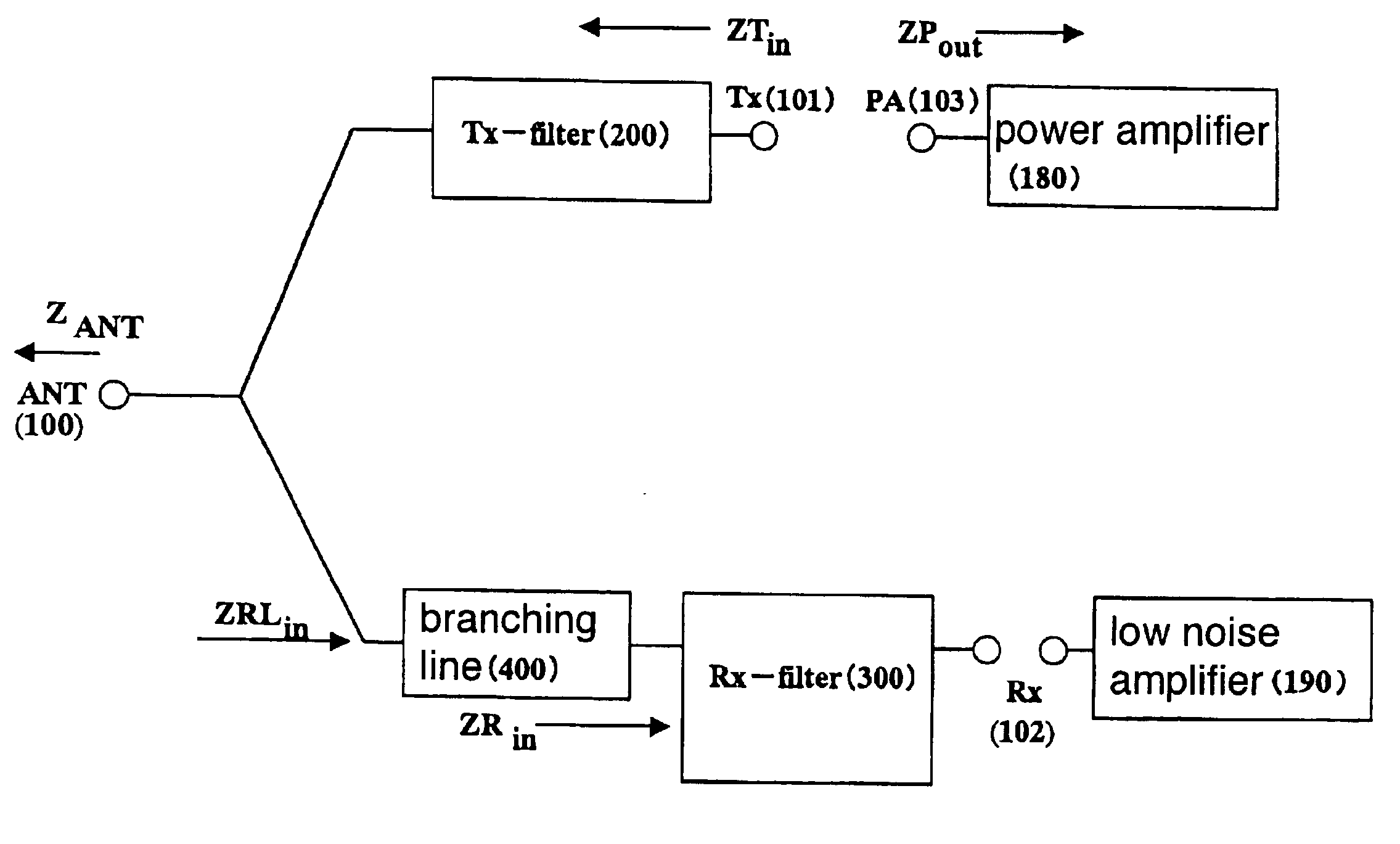
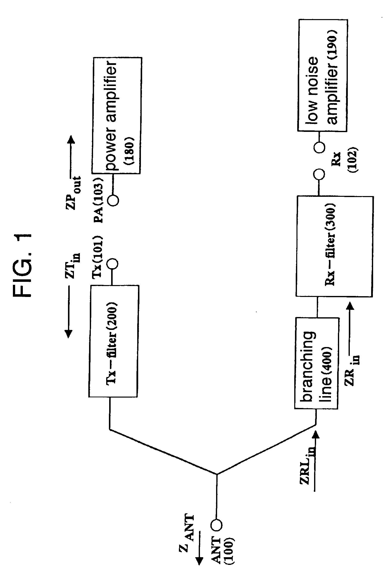
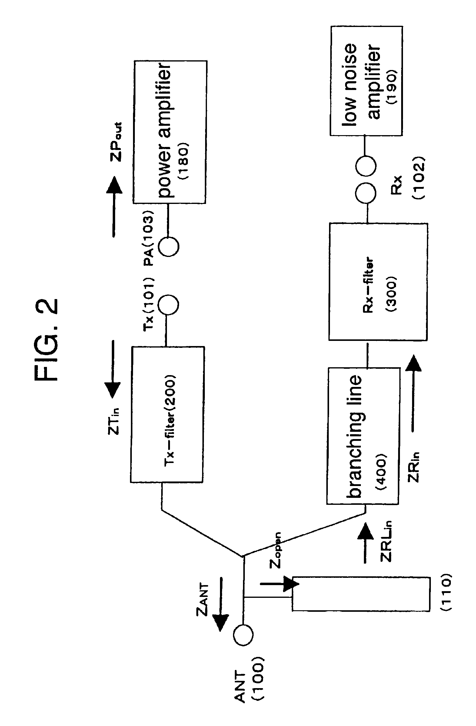
FIG. 1 is the circuit block diagram relating to the invention.

In FIG. 1, in the mobile communication terminals such as portable telephones, normally the output impedance ZPout at the output terminal (PA terminal) (103) of a power amplifier (180) is defined as 50Ω. It is generally known that the output power of the power amplifier (180) is the sum of a power inputted into the Tx filter (200) from the Tx terminal (101) of the SAW branching filter and a power reflected to the PA terminal (103) of the power amplifier (180) from the Tx terminal (101) of the SAW branching filter, on the basis of the relation between the input impedance ZTin of the Tx filter and the output impedance ZPout of the power amplifier (180).

In the mobile communication terminals such as portable telephones in FIG. 1, the input impedance Zant of an antenna (170) connected to the antenna terminal (ANT terminal) (100) is designed as 50Ω. However in practice, it is known that the impedance varies from 50Ω to infinite....


PUM


Abstract

A surface acoustic wave filter includes an antenna terminal, an antenna, a transmitting filter, a branching line and a receiving filter. The antenna is coupled to the antenna terminal. The transmitting filter is coupled to the antenna terminal. The transmitting filter receives an electrical power. The branching line is coupled to the antenna terminal. The branching line has a first length that is longer than λ / 4 length so that the electrical power received by the transmitting filter when the antenna terminal is opened is smaller than when the antenna terminal is terminated, wherein λ is a wave length of a center frequency of transmitted and received bands of the surface acoustic wave filter. The receiving filter is coupled to the branching line.

Description

BACKGROUND OF THE INVENTION1. Field of the InventionThe present invention relates to a surface acoustic wave filter using a ladder type band pass filter that uses a surface acoustic wave resonator in small mobile communication equipment such as portable telephones, specifically to a surface acoustic wave filter that can be used even with a high power applied.2. Description of the Background ArtThere have been keen and energetic developments of small and lightweight mobile communication terminals such as portable telephones. The developments have involved demands for smaller parts and higher performances of the components used. These demands result in developments of RF (radio frequency) components using the surface acoustic wave (SAW) filter, which are used in practice. The SAW filter is a device that makes a great contribution to miniaturization of the RF units, which has been actively developed and used partly in some areas.The recent improvements of performances in the mobile com...

Claims


Application Information

Patent Timeline
Patent Type & Authority Patents(United States)
IPC IPC(8): H03H9/00H03H9/64H03H9/72
CPCH03H9/6483
Inventor OHASHI, WATARUEHARA, HISANORIKOMAZAKI, TOMOKAZU
Owner INTELLECTUAL VENTURES HOLDING 81 LLC
Learn More