
Ferroelectric antenna and method for tuning same

a ferroelectric antenna and antenna technology, applied in the field of wireless communication antennas, can solve the problems of ferroelectric tunable components operating in rf or microwave regions that are perceived as particularly lossy, and the loss of most fe materials

Inactive Publication Date: 2005-03-01
KYOCERA CORP
View PDF55 Cites 11 Cited by
  • Summary
  • Abstract
  • Description
  • Claims
  • Application Information

AI Technical Summary

Problems solved by technology

Under presently used measurement and characterization techniques, however, tunable ferroelectric components have gained the reputation of being consistently and substantially lossy, regardless of the processing, doping or other fabrication techniques used to improve their loss properties.
Ferroelectric tunable components operating in RF or microwave regions are perceived as being particularly lossy.
In general, most FE materials are lossy unless steps are taken to improve (reduce) their loss.
The assumption of high ferroelectric loss, however, has carried over into thin film work as well.
However, the use of FE dielectric materials has not always been effective, especially if the FE materials are not located in the regions of greatest electromagnetic filed densities.

Method used


Image

  • Ferroelectric antenna and method for tuning same
  • Ferroelectric antenna and method for tuning same
  • Ferroelectric antenna and method for tuning same

Examples


Embodiment Construction

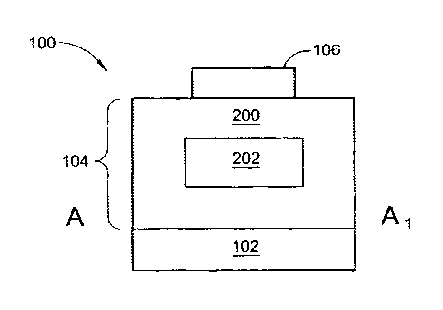
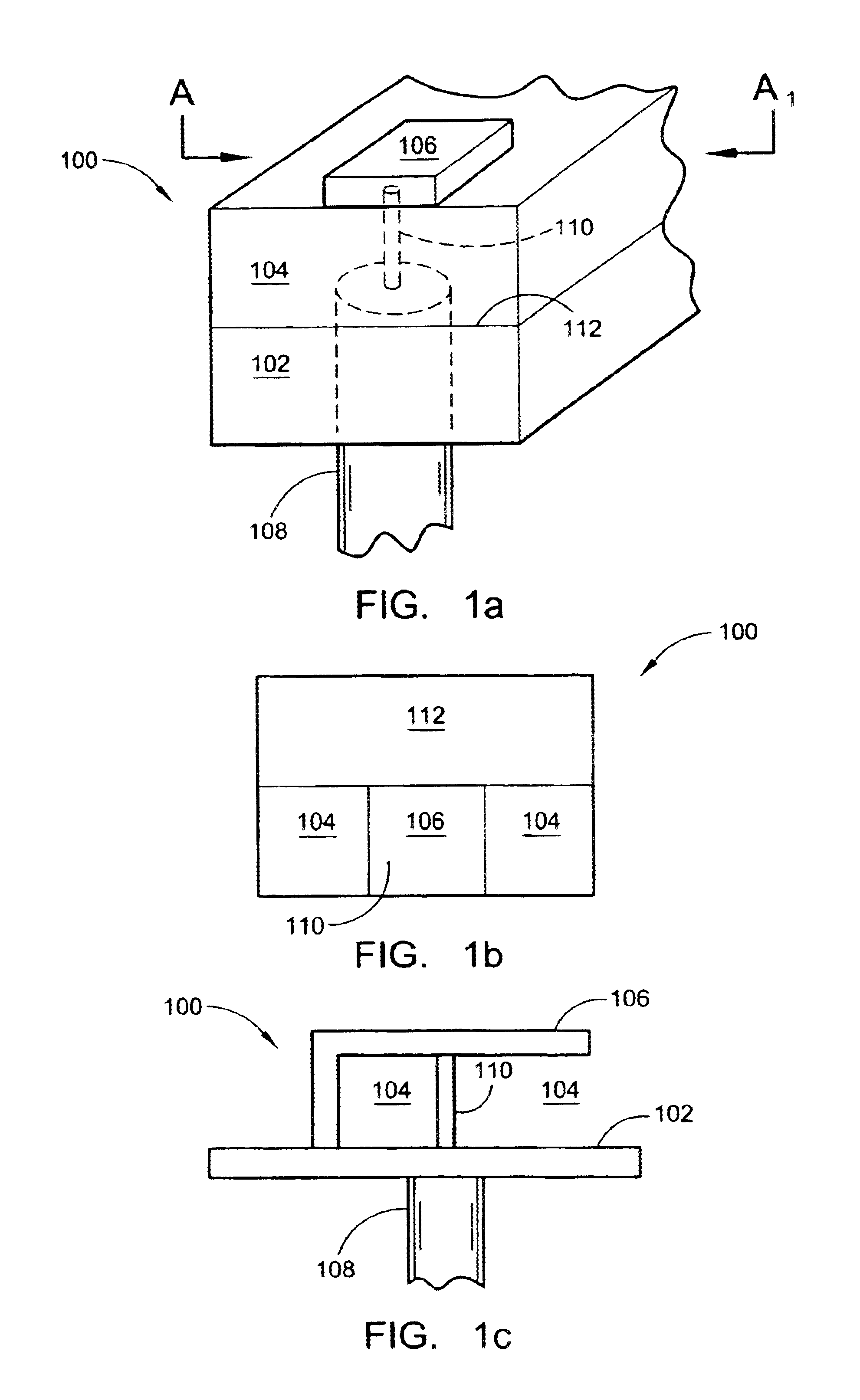
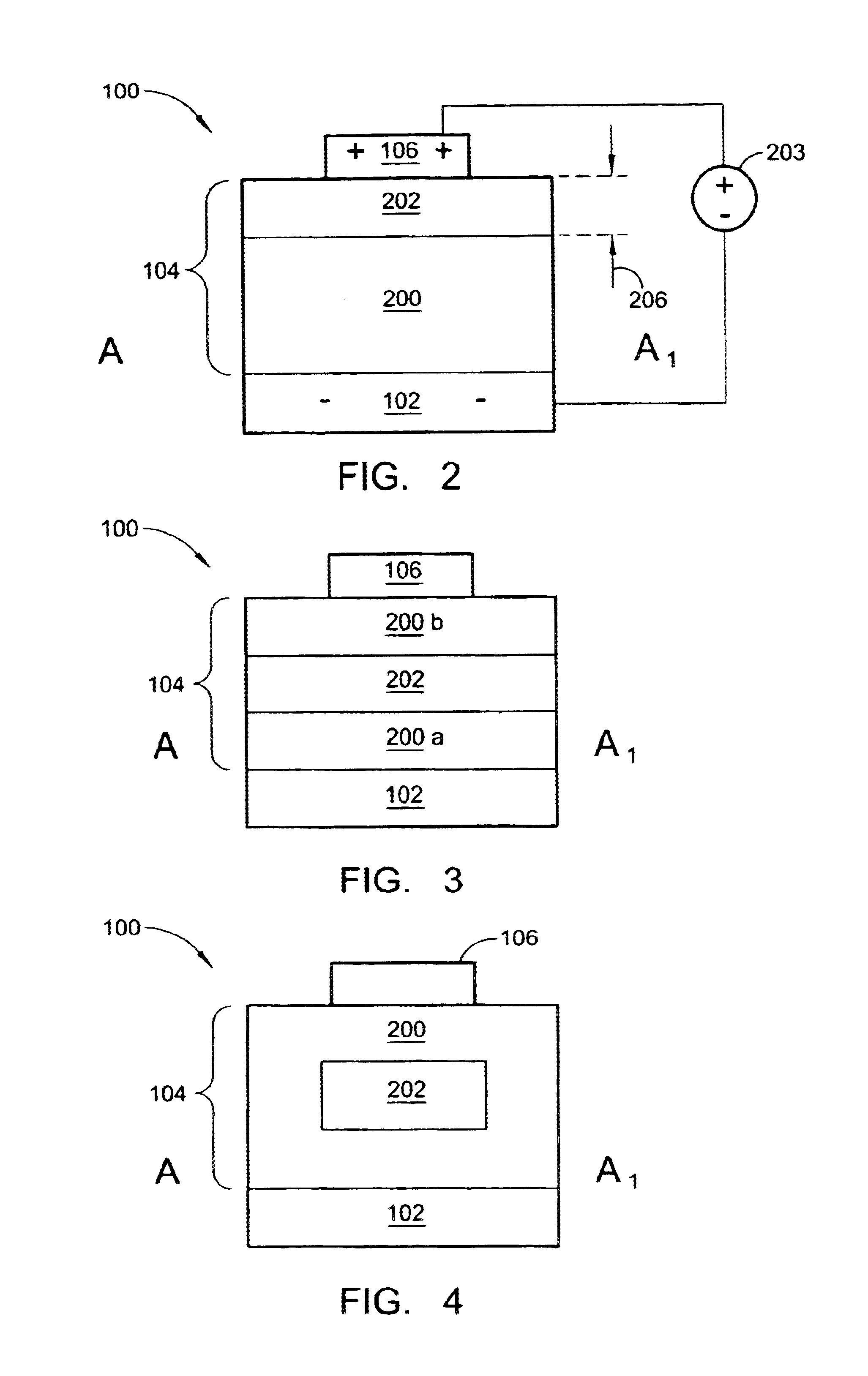
The present invention describes a family of antennas with a selectable operating frequency. Generally, each antenna includes a radiator and a dielectric with ferroelectric material proximate to the radiator having a variable dielectric constant. The radiator is resonant at a frequency responsive to the dielectric constant of the ferroelectric material. Some antennas include a counterpoise to the radiator. Other antenna designs include a counterpoise and radiator that are arbitrarily designated. Yet other designs include a counterpoise and radiator that are not distinctly distinguishable from each other.

In one aspect of the present invention, the family of antennas presented below have an FE dielectric layer included to effectively tune the resonant frequency of a single-radiator antenna, unlike prior art antennas which rely upon multiple radiators to achieve any appreciable bandwidth or resonant frequency change. The present invention single-radiator antennas are defined herein as s...


PUM

PropertyMeasurementUnit
thicknessaaaaaaaaaa
thicknessaaaaaaaaaa
resonant frequencyaaaaaaaaaa

Abstract

A family of FE dielectric-tuned antennas and a method for frequency tuning a wireless communications antenna are provided. The method comprises: forming a radiator; forming a dielectric with ferroelectric material proximate to the radiator; applying a voltage to the ferroelectric material; in response to applying the voltage, generating a dielectric constant; and, in response to the dielectric constant, communicating electromagnetic fields at a resonant frequency. Some aspects of the method further comprise: varying the applied voltage; and, modifying the resonant frequency in response to changes in the applied voltage. Modifying the resonant frequency includes forming an antenna with a variable operating frequency responsive to the applied voltage. Alternately stated, forming an antenna with a variable operating frequency includes forming an antenna with a predetermined fixed characteristic impedance, independent of the resonant frequency.

Description

BACKGROUND OF THE INVENTION1. Field of the InventionThis invention generally relates to wireless communication antennas and, more particularly, to a system and method for tuning an antenna with the aid of a ferroelectric dielectric material.2. Description of the Related ArtThere are several types of conventional antenna designs that incorporate the use of a dielectric material. Generally speaking, a portion of the field that is generated by the antenna returns to the counterpoise (ground), from the radiator, through the dielectric. The antenna is tuned to be resonant at frequencies, and the wavelengths of the radiator and dielectrics have an optimal relationship at the resonant frequency. The most common dielectric is air, with a dielectric constant of 1. The dielectric constants of other materials are defined with respect to air.Ferroelectric materials have a dielectric constant that changes in response to an applied voltage. Because of their variable dielectric constant, ferroelec...

Claims


Application Information

Patent Timeline
Patent Type & Authority Patents(United States)
IPC IPC(8): H01Q13/00H01Q9/04H01Q9/28H01P1/203H03B5/36H01Q13/22H01Q13/20H01Q3/44H01Q9/16H01P1/20H01Q13/06H01Q13/02H01Q9/30H03F1/00H03F3/191H03L1/02H03F3/189H01Q3/00H03L1/00H03J5/24H03F1/56H03J5/00H03L7/18H03L7/16H03B5/18H03H7/01H03H7/12H01G4/12G01R27/26H01G4/33H01G4/40H01G7/06H01L27/08H01P1/205H01P1/213H01P1/36H01P5/04H01P7/08H01Q1/00H01Q1/24H01Q1/38H01Q9/14H01Q9/42H01Q13/08H03B5/04H03B5/08H03B5/12H03H7/20H03H7/38H04B1/04H04B1/30H04B1/40H04L27/38
CPCG01R27/2694H01L27/0808H01P1/203H01P1/20336H01P1/20363H01P1/20381H01P1/2039H01P1/2056H01P1/213H01P5/04H03B5/04H03B5/1841H03B5/362H03F1/56H03F3/191H03H7/20H03J5/246H03L1/022H03L7/18H04B1/0458H04B1/30H03B5/124H03B5/1293H03B5/1262H04B1/40H01G7/06H03F2200/111H03F2200/294H03F2200/372H03H7/0123H03H7/12H04B1/0053H01Q9/04
Inventor TONCICH, STANLEY S.TRAN, ALLEN
Owner KYOCERA CORP
Learn More