Patient support apparatus

a technology for supporting equipment and patients, which is applied in the direction of patient positioning for diagnostics, instruments, applications, etc., can solve the problems of too expensive to procure an array of specialized equipment to accommodate a small number of bariatric patients

Inactive Publication Date: 2005-03-08
WLF
View PDF50 Cites 91 Cited by
  • Summary
  • Abstract
  • Description
  • Claims
  • Application Information

AI Technical Summary

Benefits of technology

Thus, the patient support apparatus of the present invention has two basic modes of movement. In a first mode of movement, the patient support assembly rotates relative to the base frame so that a patient in a horizontal position may be raised to an upright, standing position. A patient who has been lifted to an upright position can easily step off from the apparatus and begin walking. In a second mode, a patient supported by the apparatus may be supported in a flat, supine p

Problems solved by technology

It is too costly to procure an array of specialized items of

Method used


Image

  • Patient support apparatus
  • Patient support apparatus
  • Patient support apparatus

Examples


Embodiment Construction

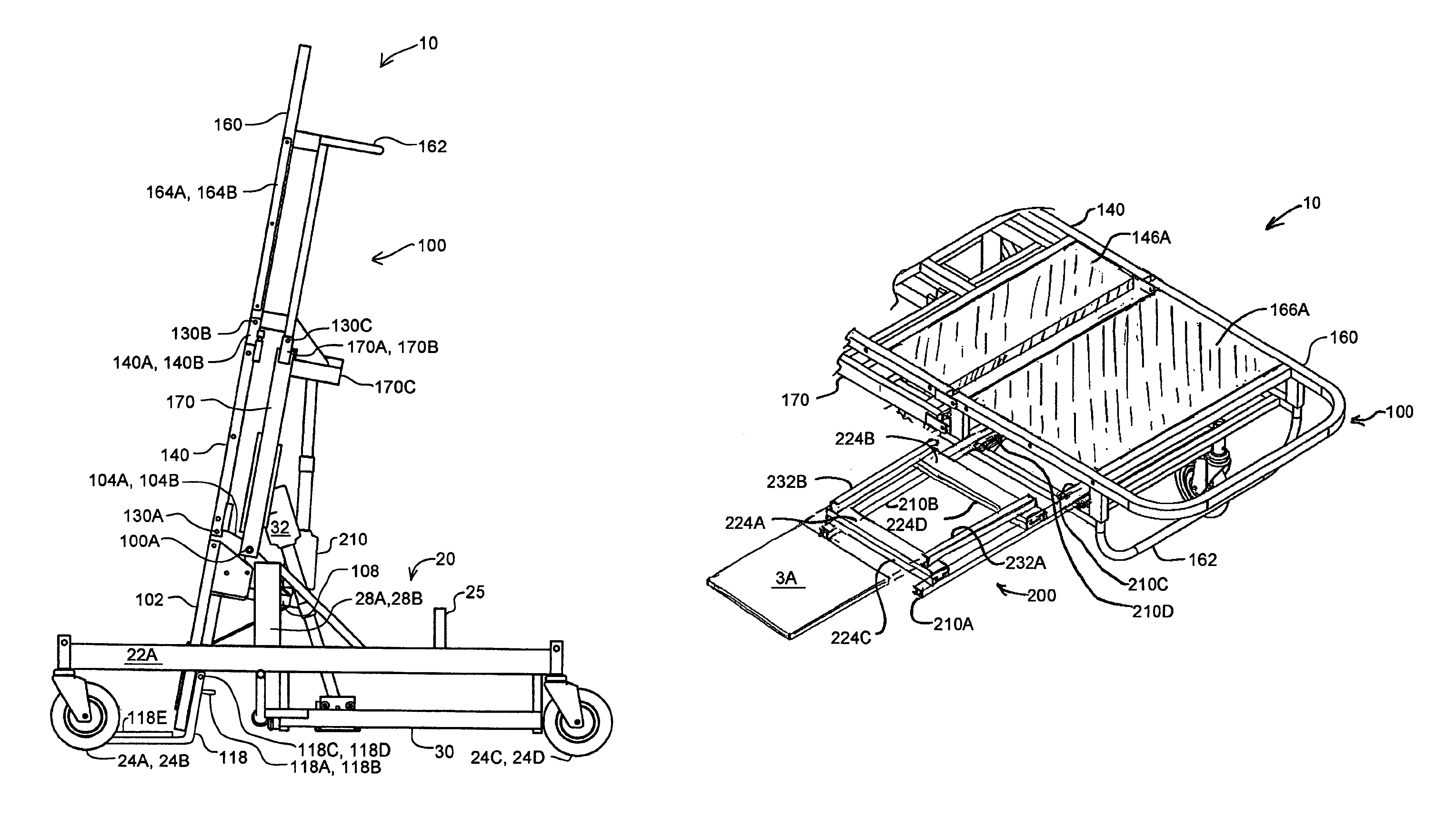
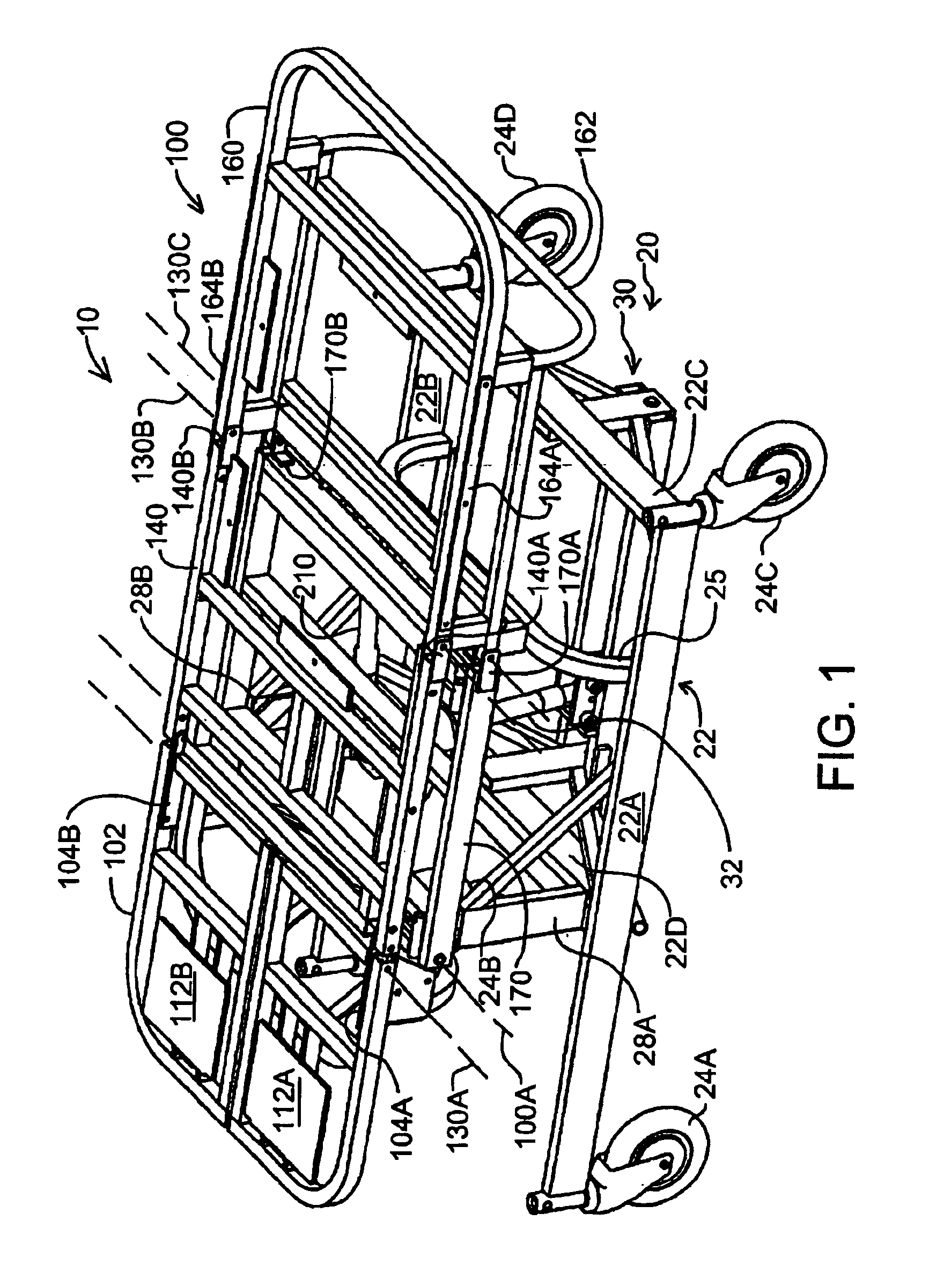
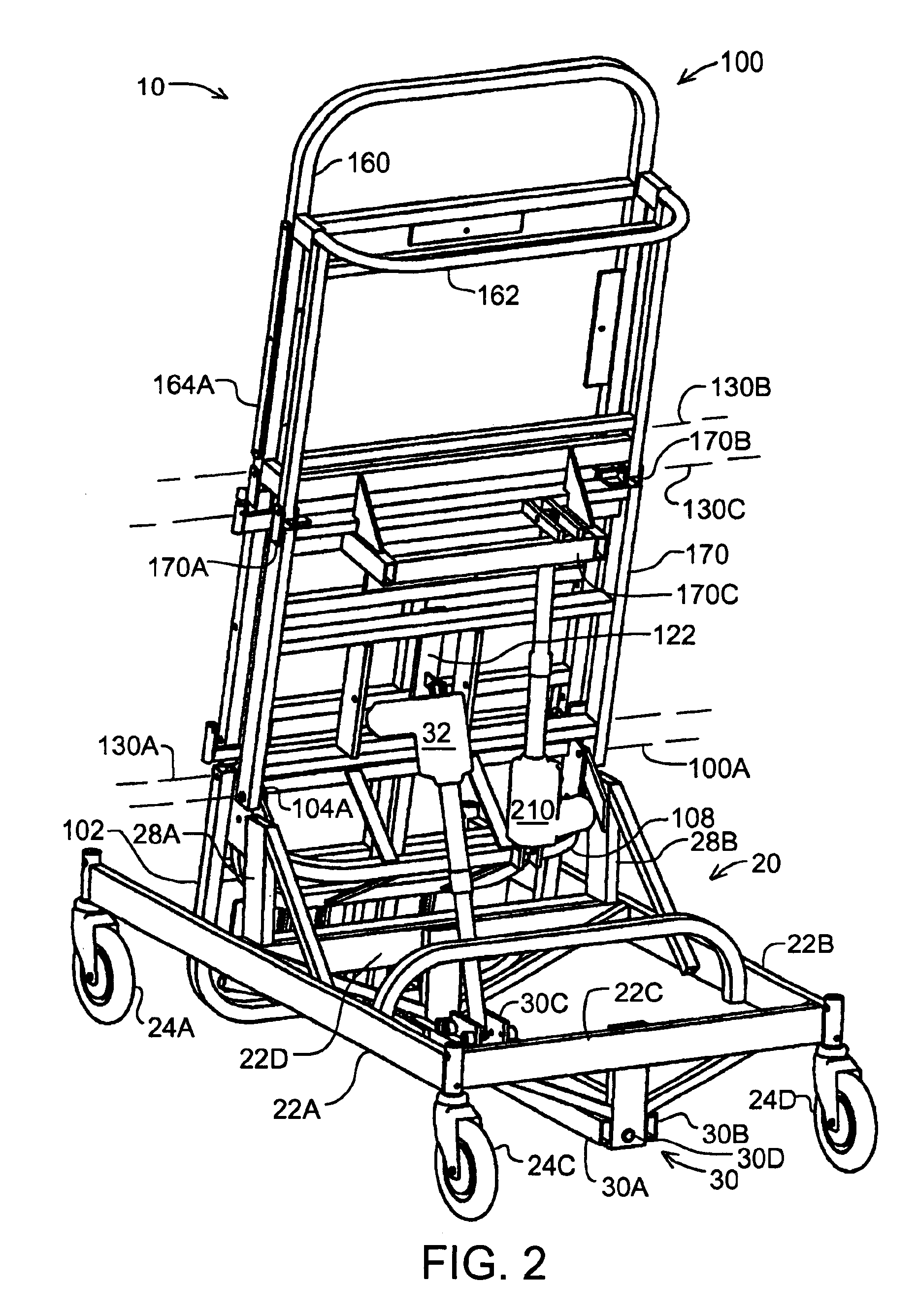
Turning now to the drawings, wherein like reference numerals identify identical or corresponding elements, and more particularly to FIG. 1 thereof, a patient support apparatus 10 is shown having a base frame 20 and a patient support assembly 100.

As shown in FIGS. 1 and 2, base frame 20 includes a horizontal rectangular carriage 22, upright members 28A and 28B, a support member 25 and an actuator support structure 30. Rectangular carriage 22 is a rigid structure including two side members 22A and 22B, an end member 22C and a transverse member 22D. Carriage 22 is supported by wheel assemblies 24A, 24B, 24C and 24D. Wheel assembly 24C and 24D are caster wheels that allow carriage 22 to turn. Upright members 28A and 28B are fixed to side members 22A and 22B. At the top end of upright members 28A and 28B are bearings for receiving pins (not shown) which are common to patient support assembly 100. Support member 25 arches between side members 22A and 22B and provides a second support for ...


PUM


Abstract

The patient support apparatus includes a base frame and a patient support assembly. The patient support assembly is pivotably mounted the base frame and is moved by a first actuator to rotate between a horizontal position and an upright position. The patient support assembly includes an upper body portion, a lower body portion and a leg portion. The upper body portion, the lower body portion and the leg portion are pivotably interconnected with a linkage frame so that they can be moved in unison by a second actuator between a supine configuration and an upright, chair shaped configuration. Thus, the patient support apparatus is adjustable between a flat, bed shaped configuration and a seat shaped configuration and is also movable between a horizontal position and an upright position.

Description

FIELD OF THE INVENTIONThis invention relates to an articulated patient support apparatus having a first function for, moving patient supporting surfaces between a first flat configuration and a second chair shaped configuration and a second function for moving the patient supporting surfaces between a first horizontal position and a second upright position.BACKGROUND OF THE INVENTIONHospitals and other care facilities use items of equipment to move and support patients. Typically, such items of equipment tend to be specialized items of equipment including hospital beds, wheelchairs, gurneys and operating tables.Hospitals and other care facilities occasionally have a need to support and move “bariatric” patients having body weights in excess of 300 lbs. It may be cost efficient for a hospital or care facility to procure an array of specialized equipment such as beds, wheelchairs, gurneys and operating tables to support or move non-bariatric patients. It is too costly to procure an ar...

Claims


Application Information

Patent Timeline
IPC IPC(8): A61G7/015A61G7/002A61G7/005A61B6/04
CPCA61B6/0442A61G7/015A61G7/005A61G2200/36
Inventor JOHNSON, MICHAEL KARLPARSON, TROY DELL
Owner WLF
Why Eureka
Try Eureka