Power mower with riding platform for supporting standing-operator

a technology of standing operator and mower, which is applied in the direction of mowers, agricultural tools and machines, and mowers. it can solve the problems of operator's feet being left unprotected, potentially dangerous flying debris, and mowers controlled by walking operators. it is less susceptible to impacting the ground

Inactive Publication Date: 2005-03-08
WRIGHT MFG
View PDF43 Cites 10 Cited by
  • Summary
  • Abstract
  • Description
  • Claims
  • Application Information

AI Technical Summary

Benefits of technology

a riding platform fixedly mounted on the mower for supporting the standing-occupant, the platform being located between the first and second rear drive wheels during operation of the mower so that when the standing...

Problems solved by technology

Unfortunately, the operator of walk-behind mowers such as these is forced to continually walk during mowing operations, thereby leading to fatigue.
This is, of course, a disadvantage associated with walk-behind mowers, especially in hilly environments.
As a result of operator fatigue, mowers controlled by walking operators are generally less productive over extended periods of time.
A further disadvantage of walk-behind mowers is that the operator's feet are left unprotected and thus exposed to potentially dangerous flying debris.
Unfortunately, seated occupant operated mowers tend to have fairly high centers of gravity (i.e. they are top heavy) due to the position of the operator's center of gravity which is far from the ground.
Such high centers of gravity render mowers operated by seated occupants more likely to tip or roll.
Operation at reduced speeds clearly leads to reduced productivity of the mower.
Additionally, seated operators have a hard time ducking under low hanging tree limbs and the like because of the fixed position of the seat and thus the lower half of the operator's body.
Furthermore, seat assemblies on such mowers necessarily increase the overall cost of the mowers.
While the trailing platforms or sulky devices of U.S. Pat. Nos. 2,354,576 and 5,004,251 provide for mower operation by a standing-occupant, they greatly extend the overall length of the mower system and are rather bulky in nature.
This is extremely burdensome and inconvenient.
A further problem with removable trailing platforms such as those disclosed in U.S. Pat. Nos. 5,004,251 and 2,354,576 is that they significantly extend the length of the mower thereby decreasing maneuverability in tight spaces.
Additionally, because these sulky or attachment devices are not actually part of the mower, they must often be purchase...

Method used


Image

  • Power mower with riding platform for supporting standing-operator
  • Power mower with riding platform for supporting standing-operator
  • Power mower with riding platform for supporting standing-operator

Examples


Embodiment Construction

Referring now more particularly to the accompanying drawings in which like reference numerals indicate like parts throughout the several views.

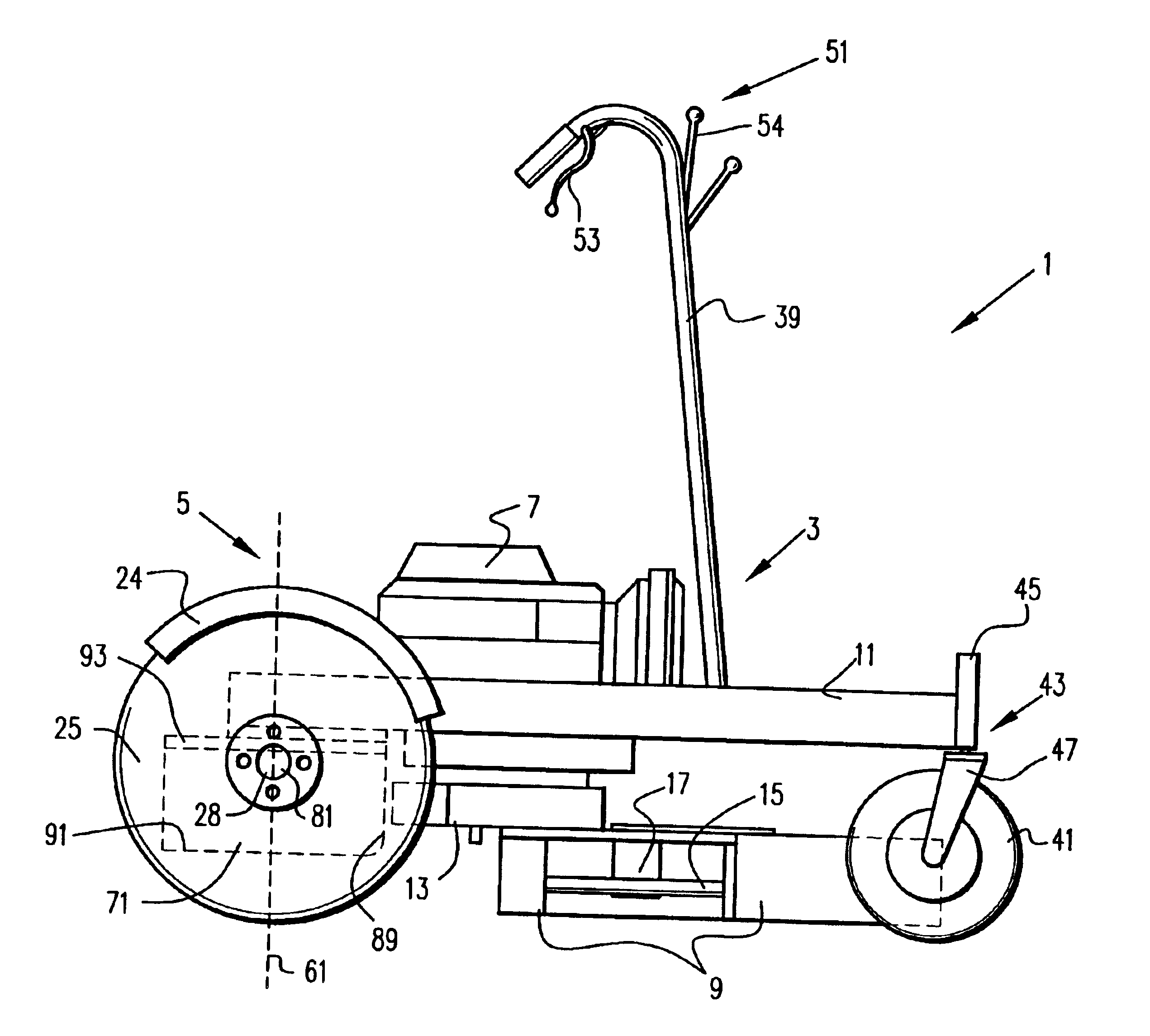
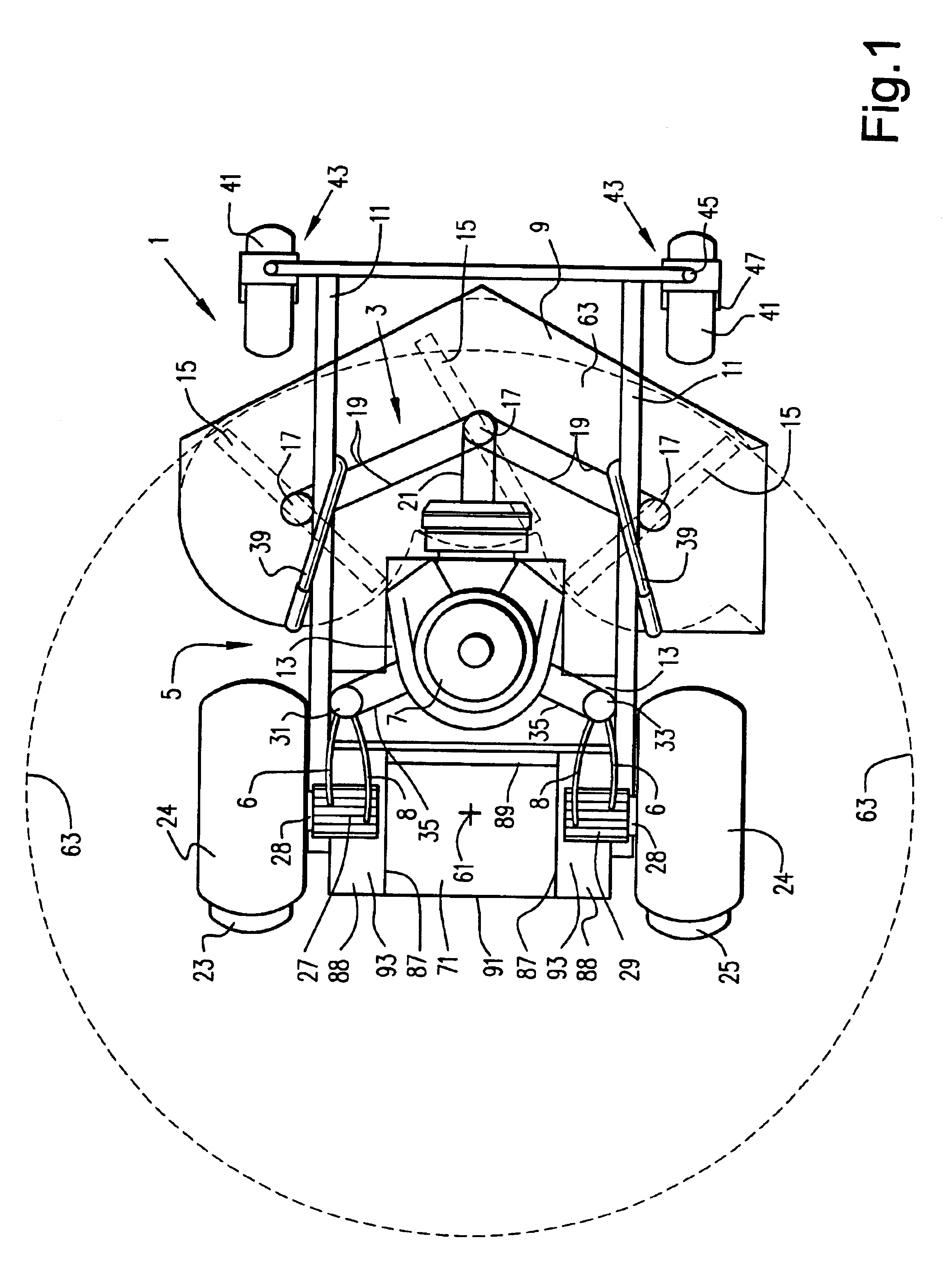
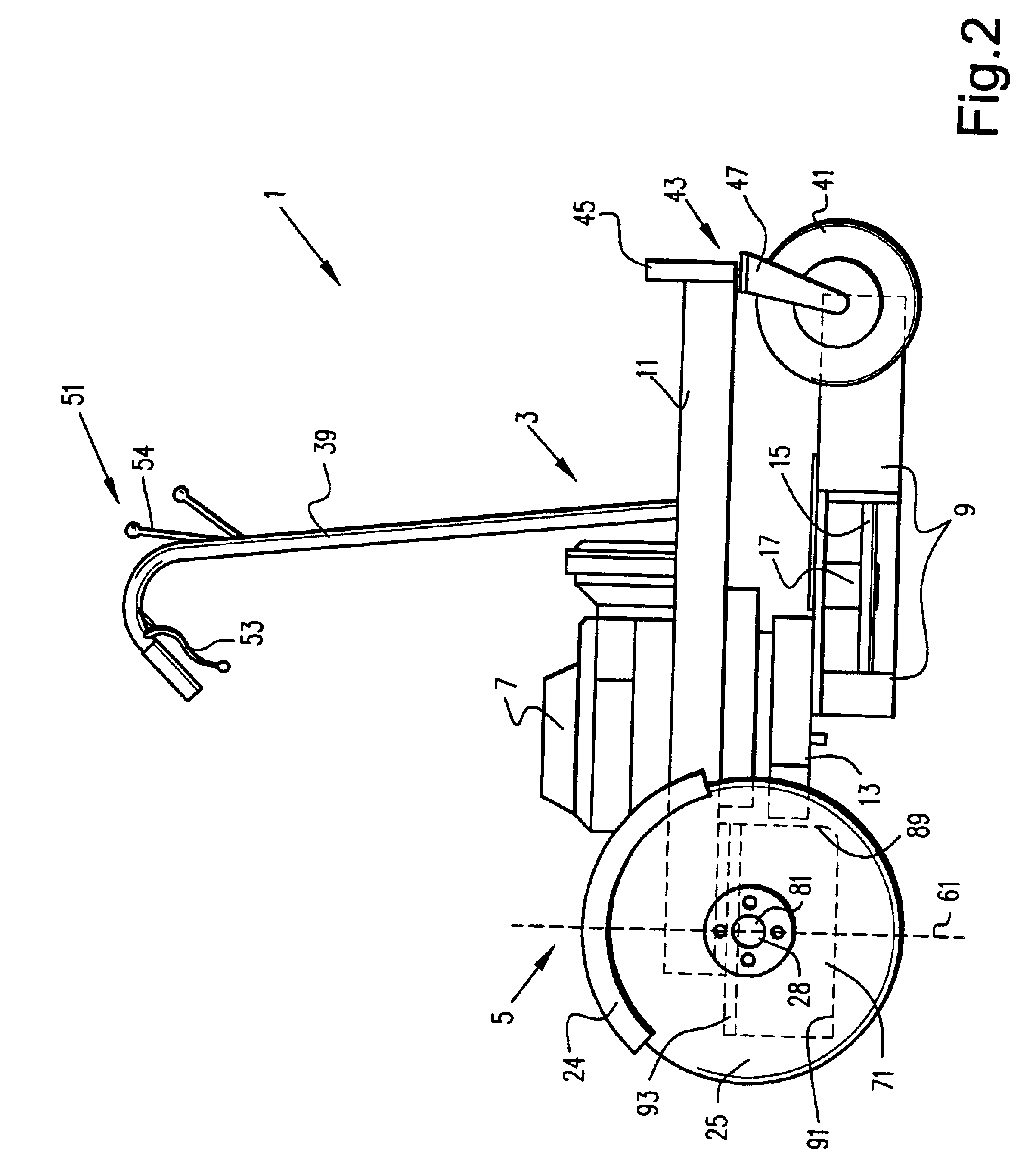
FIGS. 1 and 2 are top and side views respectively of power lawn mower 1 according to a first embodiment of this invention. Power lawn mower 1 includes cutter assembly 3 and drive assembly 5.

Cutter assembly 3 includes engine 7 and cutter or mower deck 9. Mower deck 9 is mounted on and below frame 11 in front of engine 7 and engine deck 13. Mower deck 9 is positioned close to the ground below engine deck 13, engine 7, and frame 11 in certain embodiments of this invention. In the first embodiment as shown in FIG. 2, mower deck 9 is mounted on and connected to both engine deck 13 and frame 11. Frame 11 includes a pair of substantially parallel frame members which extend longitudinally along mower 1. Mower deck 9 (or alternatively the mower wheels) is vertically moveable or adjustable so as to adjust the height of the cut. Deck 9 may be about 36-7...


PUM


Abstract

A zero-turning-radius power lawn mower for operation by a standing-occupant includes first and second independently driven and controlled rear drive wheels mounted on separate drive axles. A riding platform for supporting the standing-occupant or operator is located between the first and second rear drive wheels. The rear drive wheels are independently driveable in both the forward and reverse directions at variable speeds so as to allow for substantially zero-radius-turning of the mower about a central turning point. The riding platform is positioned at this turning point so that the standing-occupant remains substantially unaffected by centrifugal force created during approximate zero-radius-turning of the mower thereby allowing the mower to take such turns at higher speeds. Such positioning of the platform also provides for improved maneuverability, reduces the likelihood that the platform will bottom out when the mower goes over bumps, and creates a safer mower less susceptible to tipping due to the resulting low center of gravity. The low center of gravity created by the position of the riding platform for the standing-operator also results in the mower having improved traction and being less likely to pop “wheelies” upon acceleration.

Description

This invention relates to a power driven device. More particularly, this invention relates to a power lawn mower including a riding platform for supporting a standing-operator.BACKGROUND OF THE INVENTIONConventional hydraulically driven or hydrostatically controlled machines such as power lawn mowers include a pair of drive wheels, each of which is independently operated by a hydraulic or hydrostatic pump coupled to the mower's engine. A corresponding motor is provided for each drive wheel, each motor being powered by one of the pumps. Each pump includes a control lever for regulating fluid pressure and direction to its corresponding motor. In such a manner the drive wheels of the power device (e.g. lawn mower) are independently controlled so that each may be rotated at variable speeds in both forward and reverse directions.Accordingly, each drive wheel of hydrostatically controlled mowers may be driven in either the forward or reverse direction and the mower may therefore be turned...

Claims


Application Information

Patent Timeline
IPC IPC(8): A01D34/00A01D34/82A01D34/63A01D34/67A01D34/69A01D34/68A01D34/66B62D51/04B62D51/00B62D51/02
CPCA01D34/001A01D34/66A01D34/6806A01D34/69B62D51/04B62D51/02A01D34/82A01D2034/6843A01D2101/00
Inventor WRIGHT, WILLIAM R.VELKE, JAMES
Owner WRIGHT MFG
Why Eureka
Try Eureka