Self-adjusting hand tools utilizing a cam

Inactive Publication Date: 2005-03-08
I D L TECH TOOLS
View PDF11 Cites 32 Cited by
  • Summary
  • Abstract
  • Description
  • Claims
  • Application Information

AI Technical Summary

Benefits of technology

Additionally, the nature of the toggle joint provides the force augmentation mechanism whereby the force applied by the user is enhanced. That is, during the second phase as the toggle angle approaches 180 degrees, the theoretical force approaches infinity. Due to frictional forces, infinite force is not reached, but the closing force is still higher than the force applied by the user.

Problems solved by technology

The disadvantage of pliers which utilize a pawl to form the second pivot point is that such pliers are subject to a periodic force variation as the pawl engages the rack.
That is, because the teeth on the rack are disposed at fixed incremental locations and because the pawl moves over the rack teeth, the pawl may not be positioned to engage a tooth on the rack at the point when the jaws of the pliers contact the workpiece.
Smaller teeth, however, are weaker and may not be able to tolerate the stress placed on the tooth.
Additionally, fine teeth are difficult to manufacture and are subject to degradation from repeated use.
Further, prior art pliers have not successfully combined the self-adjusting and force augmenting features with a locking feature.

Method used


Image

  • Self-adjusting hand tools utilizing a cam
  • Self-adjusting hand tools utilizing a cam
  • Self-adjusting hand tools utilizing a cam

Examples


first embodiment

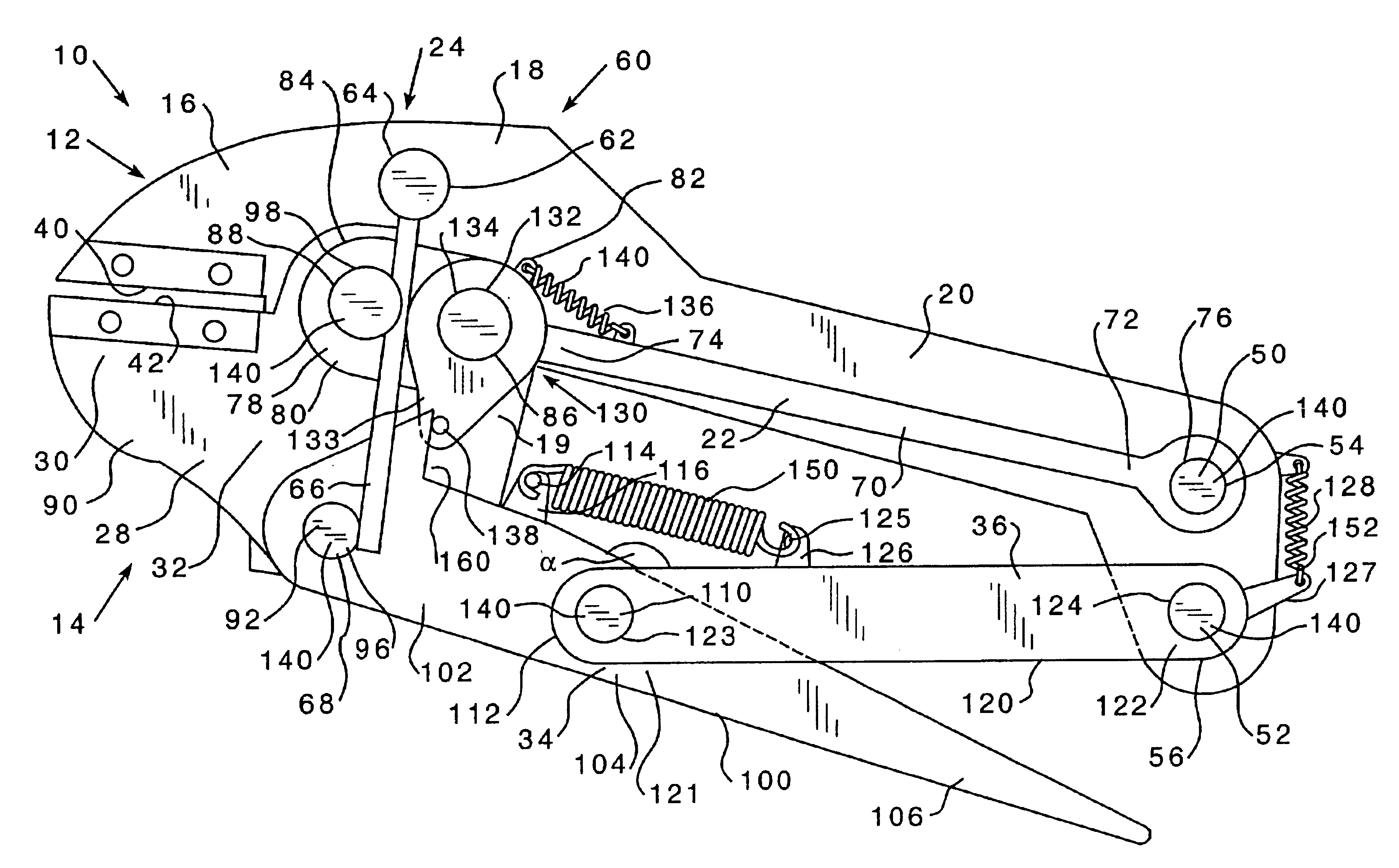
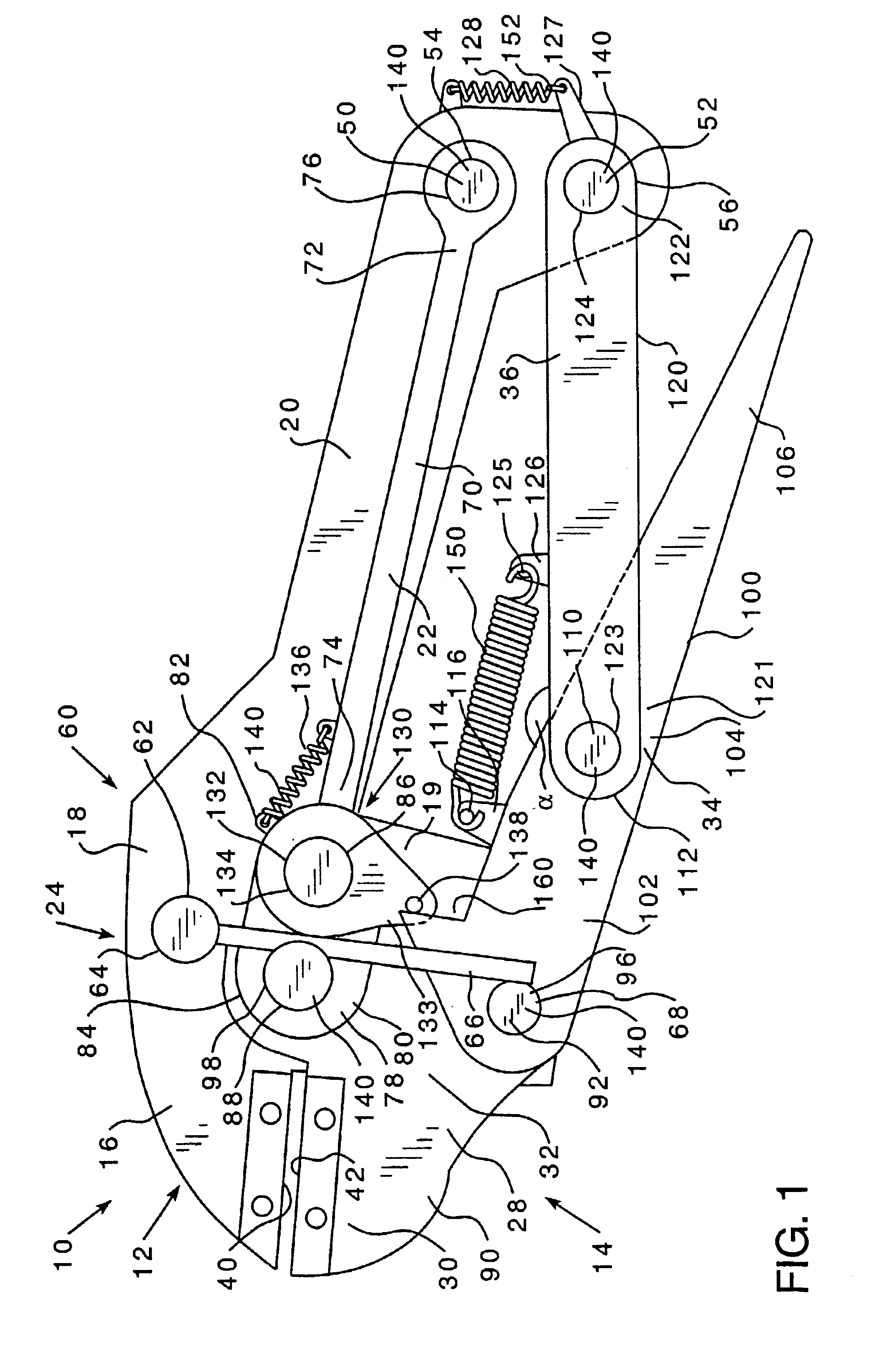
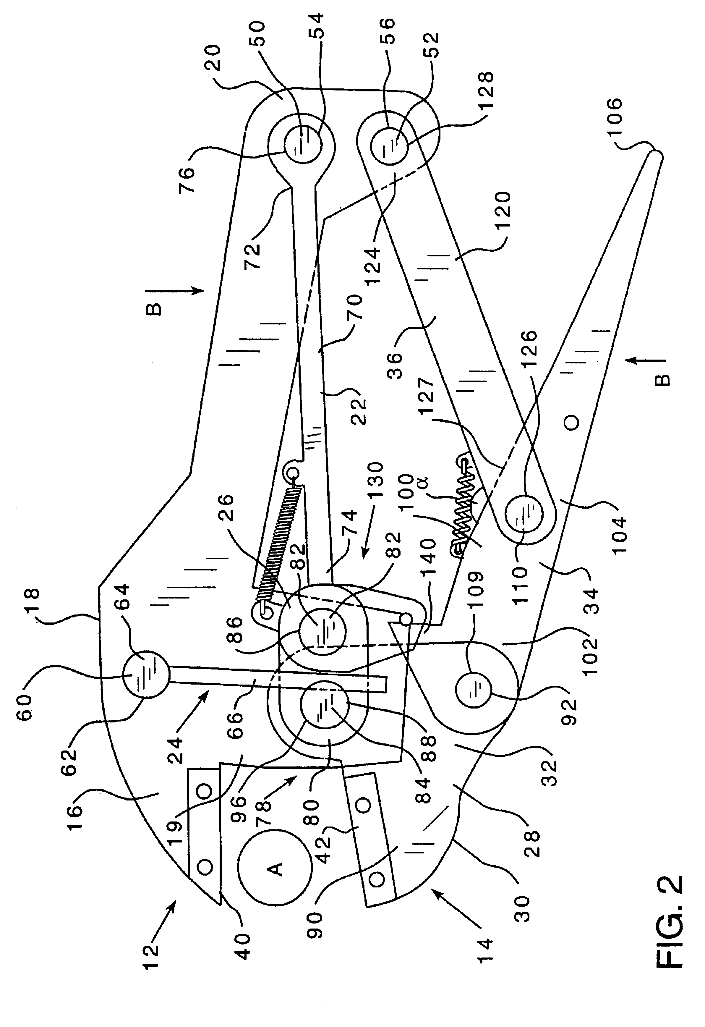
For the sake of this description, the first plier member assembly 12 shall be assumed to be in a fixed location. Thus the second plier member assembly 14 shall be described as moving relative to the first plier member assembly 12. FIGS. 2-5 show the operation of the pliers 10 that utilizes a release tab 160 extending from the second plier member assembly handle member 34 to actuate the cam assembly 130. In the first phase of operation, the jaw portions 16, 30 are initially separated and the cam assembly 130 has not engaged the tension member 66. The cam member 132 is maintained in a spaced relation from the tension member 66 by the second plier member assembly handle member release tab 160 contacting the cam assembly release pin 138. The second plier member assembly handle member 34 and the second plier member assembly second link 36 are held, relative to each other, at an initial toggle angle, indicated as α, by the toggle spring 150. With the second plier member assembly handle me...

second embodiment

As shown in FIGS. 13 and 14, the pliers 10A (second embodiment shown) are preferably constructed from a plurality of laminations 300, hereinafter, the laminate pliers 310. The laminations 300 are preferably cut or stamped from a sheet of metal. The laminations 300 form the various plier components, e.g., first plier member assembly 12 and second plier member assembly 14. The laminations 300 are erected in multiple layers. Preferably, the outer layers are mirror images of each other about a single center layer. That is, as shown in FIG. 13, the laminate pliers 310 have a first side 301 and a second side 302 and the components 12, 14 are made from mirror image laminations 300 on both the first and second sides 301, 302. For example, a laminate pliers 310 first plier member assembly 312 includes two generally flat members 311A, 311B forming a jaw portion 316, an intermediate portion 318 and a handle portion 320. The two first plier member assembly members 311A, 311B are the outermost l...


PUM


Abstract

A hand tool having a first hand tool member assembly having a jaw portion, a tension assembly, and a cam assembly and a second hand tool member assembly having a jaw portion. The hand tool further has a jaw portion first pivot point coupling the first hand tool member assembly to the second hand tool member assembly and a jaw portion second pivot point coupling the first hand tool member assembly to the second member assembly. The jaw portion second pivot point located closer to the first member and second member jaw portions than the jaw portion first pivot point. The first hand tool member assembly jaw portion and the second hand tool member assembly jaw portion are structured to close together in a three-phase motion consisting of a first pivot phase, a transition phase and a second pivot phase, the first hand tool member assembly jaw portion and the second hand tool member assembly jaw portion pivot relative to each other about the jaw portion first pivot point during the first pivot phase and pivot relative to each other about the jaw portion second pivot point during the second pivot phase. The cam assembly is structured to engage the tension assembly when the first hand tool member assembly jaw portion and the second hand tool member assembly jaw portion contact a workpiece thereby initiating the transition phase between the first pivot phase and the second pivot phase wherein the rotation about the jaw portion first pivot point is halted causing the jaw portions to rotate about the jaw portion second pivot point.

Description

BACKGROUND OF THE INVENTION1. Field of the InventionThis invention relates to self-adjusting pliers having jaws which pivot about a jaw portion first pivot point during a first phase and a jaw portion second pivot point during the second closing phase and, more specifically, to a pair of pliers which utilizes a cam during the transition between the first phase of operation and the second phase of operation.2. Background InformationPliers are used to grasp or otherwise act upon a workpiece. A pair of pliers includes two elongated members joined by a pivot pin at an intersection on the medial portion of the members. One end of each elongated member forms a jaw and the other end of the elongated members forms a handle. A workpiece located between the jaws may be grasped by an operator drawing the handle portions towards each other. Hand tools have also been constructed using two elongated members which do not intersect, but which are joined by a link member, see, e.g., U.S. Pat. No. 3,...

Claims


Application Information

Patent Timeline
IPC IPC(8): B25B7/00B25B7/10
CPCB25B7/10
Inventor DELBRUGGE, JR., GERALD VINCENTCOLBURN, ERIC
Owner I D L TECH TOOLS
Why Eureka
Try Eureka