
Hammer-type stapler with cartridge

a stapler and cartridge technology, applied in the field of hammer-type staplers with cartridges, can solve the problems of increasing taking so many steps, and being easy to miss an element, and achieve the effect of reducing the chance of jamming and guiding the striking for

Inactive Publication Date: 2005-03-08
LU CHUN MING +1
View PDF10 Cites 9 Cited by
  • Summary
  • Abstract
  • Description
  • Claims
  • Application Information

AI Technical Summary

Benefits of technology

The general purpose of the present invention is to provide a new hammer-type stapler with cartridge, which has a device driving the staples vertically to guide the striking force on the staples efficiently without any other non-vertical force for reducing the opportunity of jam.
Another purpose of the present invention is to provide a design of replaceable cartridges. Such replaceable cartridge can simplify the steps of loading staples and cleaning jammed staples, also, it is safe and quickly.
The present invention was made of a lot of plastic material and simplifies the steps of manufacturing to enable the assembly line to be fast and to drop the cost of manufacturing. Moreover, it is a close module that will not be deposited with sand prolonging its useful life.
Even better, the present invention can use the same stapler to load various wide staples by using another embodiment of a cartridge for various wide staples, which could load various wide staples.

Problems solved by technology

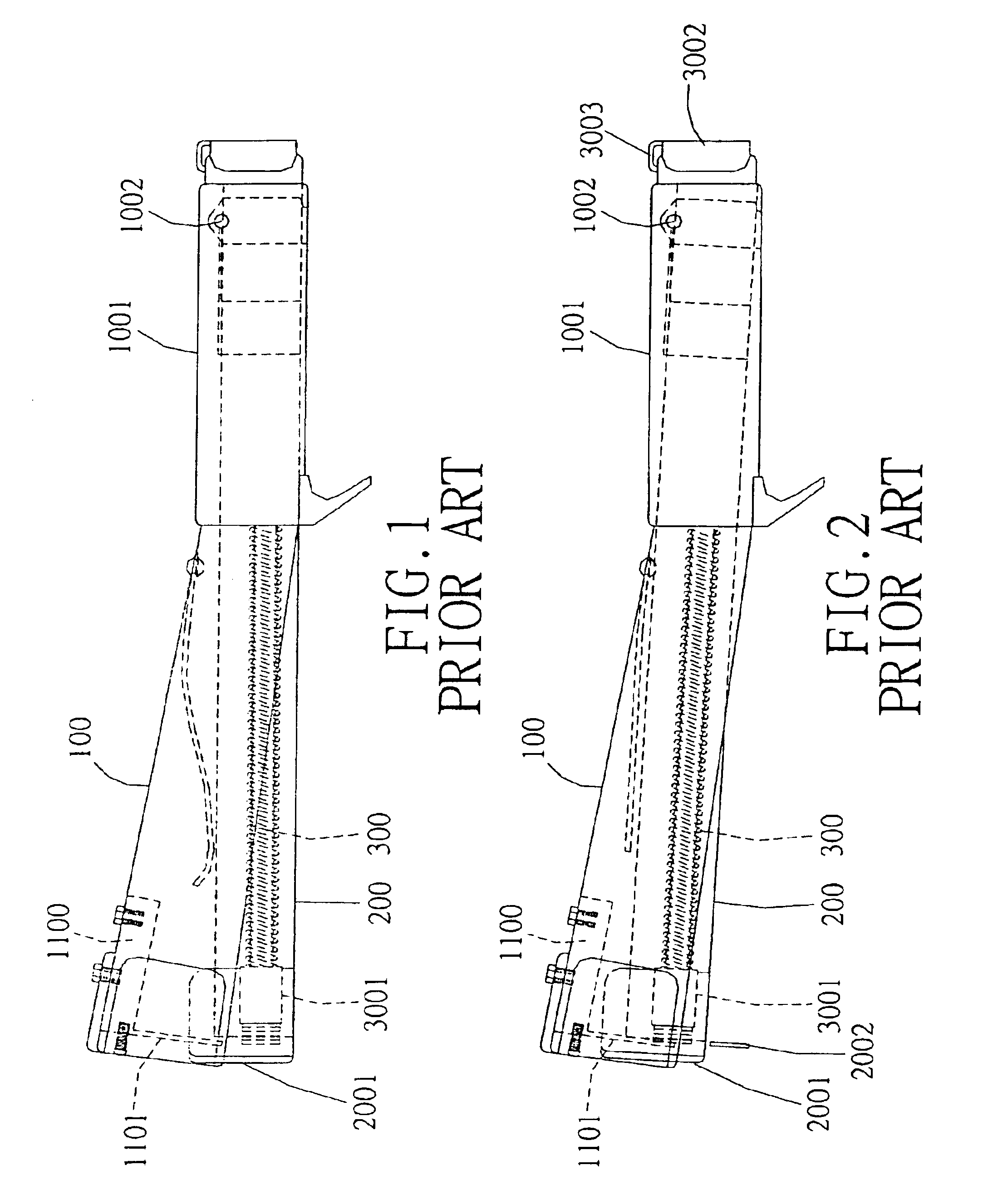
It will increase the opportunity of jam (means the staple was jammed in the driving element guiding device 2001) because of the side-direction force.
It takes so many steps and is very complicated.
When installing the elements in reverse order, it is easy to miss an element, especially when working outdoor.
This kind of stapler has the hidden danger of staple shooting out when cleaning the jam and on the other hand, it involves several jam cleaning procedure.
In addition, the elements were exposed and had much seams, so sand may be deposited at its seams result in its breakdown.
In conclusion, the disadvantages of the prior staplers are as followed:1. The movement of the driving element of the prior staplers is in a curving way and not in a vertical way.
It produces a lateral force besides the vertical force, so that it easily leads to a staple jamming.2. When cleaning the jammed staples of the prior staplers, the cleaning procedure involves much time, reducing the working efficiency.3. The prior staplers include many metal elements and many connecting procedures between those elements.
Much time and high cost are needed for its production.4. The prior staplers were limited to use staple of specific size or type, it could not use different size of staples.
Due to different factory brand, those staples may have a 5 mm difference in width, causing the staples to jam, even damaging to the tool and seriously injury to the user or others in the work area with the staple fragments.

Method used


Image

  • Hammer-type stapler with cartridge
  • Hammer-type stapler with cartridge
  • Hammer-type stapler with cartridge

Examples


Embodiment Construction

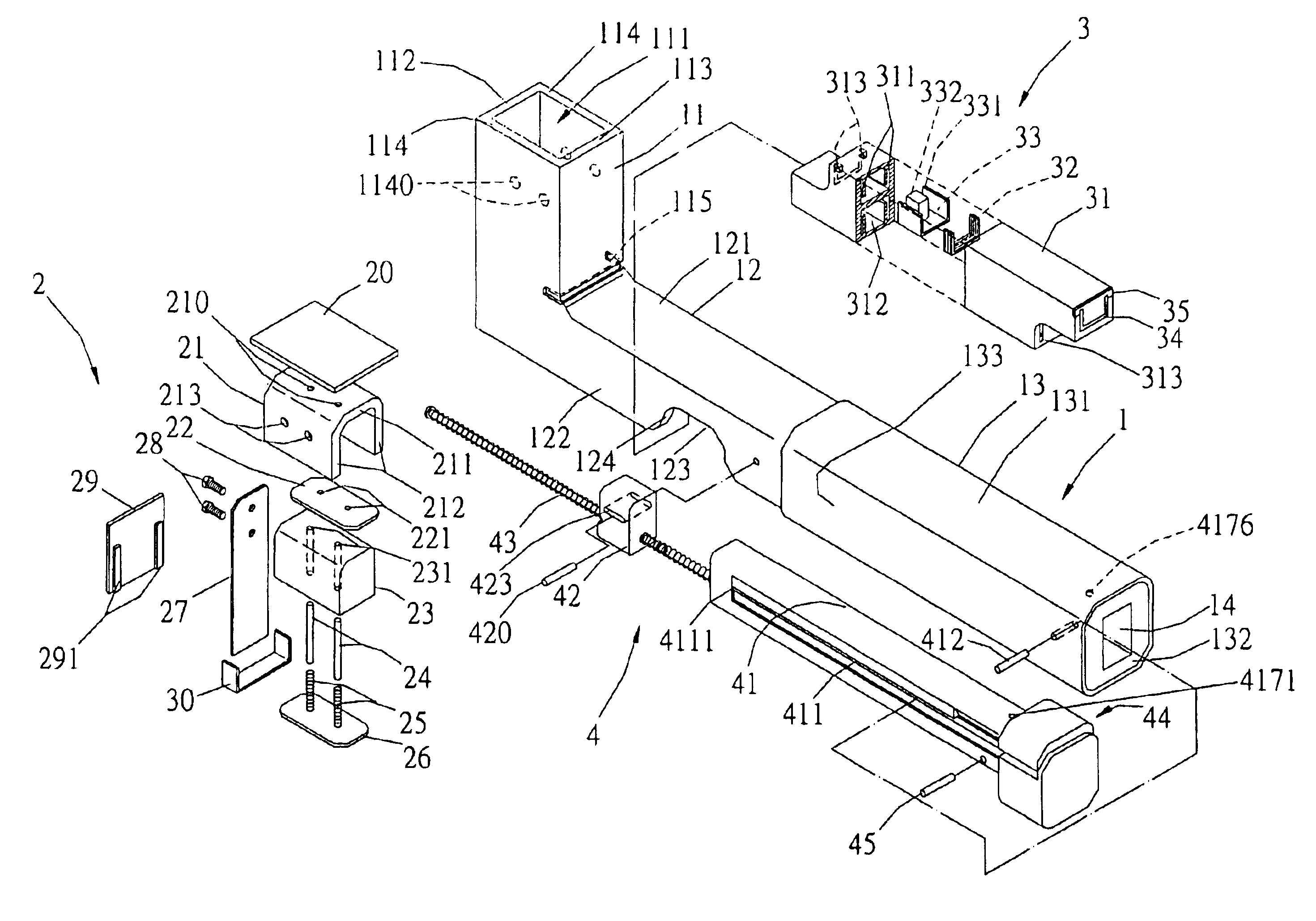
With referring now to the drawings, and in particular to FIG. 7, an exploded view of a new hammer-type stapler with cartridge according to the present invention comprises a casing 1, a driving unit 2, a cartridge 3 and a pushing device 4. The casing 1 is an integral casing having a front portion 12 and handle 13 connected with a distal end of the front portion 12, a hollow hammer casing 11 extended from an opposing end of the front portion 12. A striking unit 2 vertically mounted in the hammer casing 11. The hammer casing 11 has a front wall 112, a back wall 113, two opposing side walls 114 and an upper opening 111. A plurality of protrusion 1140 formed on an inner surface of each opposing side walls 114. The front portion 12 has a top wall 121, two opposing side walls 122 and a lower opening 123. The top wall 121 connects with the back wall 113 of the hammer casing 11 and forms a horizontal shock-shearing groove 115 thereon for reducing the vibration resulted from the working. The ...


PUM


Abstract

A hammer-type stapler with cartridge is a tool using in building working for driving staples into a working object, comprising a casing having a hollow hammer casing on the front portion of the casing for containing a driving unit. The driving unit moves vertically by inertia force and having a driving element for driving staples, and an elastic element for recoiling the driving unit. A replaceable cartridge is installed in the casing and adjacent to the driving element having two identical, upper and lower staple containers. A pushing device is slidably mounted in the casing for holding the cartridge and pushing staples. The cartridge can load different size staples.

Description

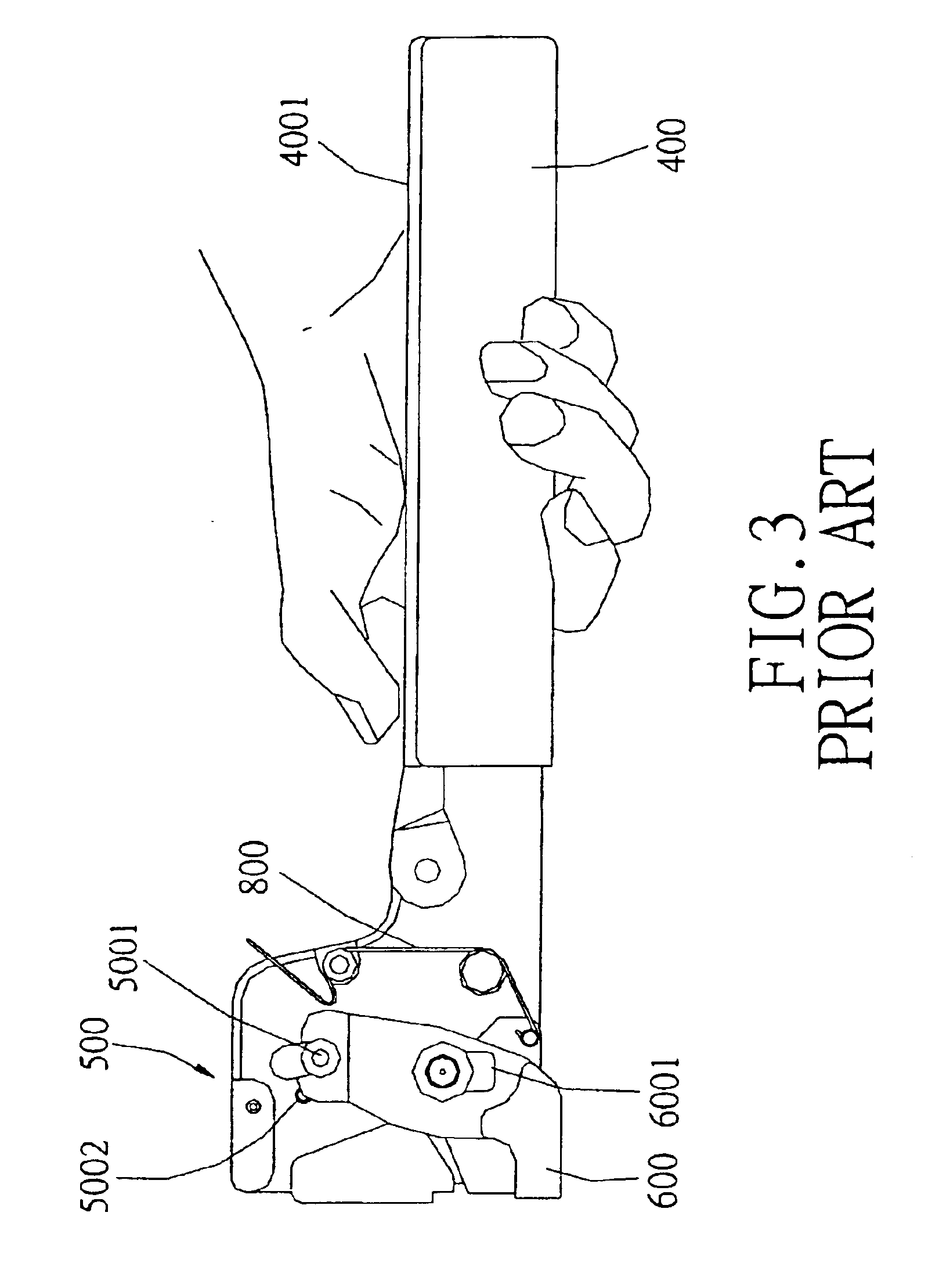
BACKGROUND OF THE INVENTION1. Field of the InventionThe present invention relates to a hammer-type stapler with cartridge and more particularly pertains to manually operated impact staplers in building, for striking staples into working piece, for example, thin board, blanket, or asphalt felt on the roof, and fix it.2. Description of the Prior ArtThe use of stapler is known in building. Hammer-type stapler is usually needed in the building site without electric power, like out door.Known prior art includes U.S. Pat. No. 3,113,117; U.S. Pat. No. 6,012,623.Two kinds of hammer-type staplers are as follow. Referring to FIG. 1 is a perspective view of the first kind of hammer-type stapler of prior art. By holding the handle 1001 and wielding the stapler to make the driving element guiding device 2001 to strike a target piece. Because of the force of inertia, the driving element 1101 will move in curving line with an axle center of the pin 1002 (referring to FIG. 2). The driving element 1...

Claims


Application Information

Patent Timeline
IPC IPC(8): B25C5/00B25C5/11
CPCB25C5/11
Inventor LU, CHUN-MING
Owner LU CHUN MING
Learn More